LG KU250 Service Manual
LG KU250 Manual
 |
View all LG KU250 manuals
Add to My Manuals
Save this manual to your list of manuals |
LG KU250 manual content summary:
- LG KU250 | Service Manual - Page 1
Service Manual Model : U250/KU250 Service Manual U250/KU250 Date: June, 2007 / Issue 1.0 - LG KU250 | Service Manual - Page 2
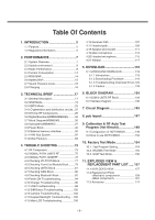
86 4.8 Checking Bluetooth Block 92 4.9 Power ON Troubleshooting 94 4.10 Charger Troubleshooting 96 4.11 USB Troubleshooting 99 4.12 SIM Detect Troubleshooting 100 4.13 Camera Troubleshooting 102 4.14 Keypad Backlight Troubleshooting ....105 4.15 Main LCD Troubleshooting 106 4.16 Receiver - LG KU250 | Service Manual - Page 3
-4- - LG KU250 | Service Manual - Page 4
steps to maintain telephone service. D. Maintenance Limitations Maintenance limitations on the phones must be performed only by the manufacturer or its authorized agent. The user may not make any changes and/or repairs expect as specifically noted in this manual. Therefore, note that unauthorized - LG KU250 | Service Manual - Page 5
provide information such as the following to the end user. F. Pictures The pictures in this manual are for illustrative purposes only; your actual hardware may look slightly different. G. Interference and Attenuation A phone may interfere with sensitive laboratory equipment, medical equipment, etc - LG KU250 | Service Manual - Page 6
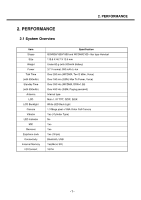
Earphone Jack Connectivity External Memory I/O Connect Specification GSM900/1800/1900 and WCDMA2100 - Bar type Handset 110.9 X 46.7 X 15.6 mm Under 83 g (with 950mAh Battery) 3.7 V normal, 950 mAh Li- Call Camera Yes ( Cylinder Type) No Yes Yes Yes (18 pin) Bluetooth, USB Yes(Micro SD) 18 Pin -7- - LG KU250 | Service Manual - Page 7
Specification 3.7 V(Typ), 3.2 V(Min), [Shut Down : 3.2 V] -20 ~ +60°C -20 ~ +70°C 85 % (Max) 2) Environment (Accessory) Reference TA Power * CLA : 12 ~ 24 V(DC) Spec . Available power Min Typ. Max Unit 100 220 240 Vac 2.3 Radio Performance 1) Transmitter - GSM Mode No Item - LG KU250 | Service Manual - Page 8
No Item GSM DCS & PCS 30M ~ 1GHz MS allocated 30M~1GHz -36dBm 1G~[A]MHz -36dBm -30dBm Radiated Channel 1G ~ 4GHz [A]M~[B]MHz -30dBm [B]M~4GHz -36dBm -30dBm 2 Spurious 30M ~ 880MHz -57dBm 30M~880MHz -57dBm Emission 880M ~ 915MHz -59dBm 880M~915MHz -59dBm Idle Mode 915M~1GHz 1G - LG KU250 | Service Manual - Page 9
2. PERFORMANCE No Item GSM DCS & PCS Frequency offset 800kHz 7 Intermodulation attenuation Intermodulation product should - be Less than 55dB below the level of Wanted signal Power control Power Tolerance Power control Power - LG KU250 | Service Manual - Page 10
2. PERFORMANCE 2) Transmitter - WCDMA Mode No Item Specification 1 Maximum Output Power Class 3 : +24dBm(+1/-3dB) OFF Power -56dBm(3.84MHz) 8 Transmit ON/OFF Time Mask ±25us PRACH,CPCH,uplinlk compressed mode ±25us 9 Change of TFC Power varies according to the data rate DTX : DPCH off - LG KU250 | Service Manual - Page 11
Intermodulation 16 Error Vector Magnitude (EVM) 17 Transmit OFF Power Specification 33dB@5MHz, ACP>-50dBm 43dB@10MHz, ACP>-50dBm -36dBm 12.2K, 1DPDCH+1DPCCH) -15dB@SF=4.768Kbps, Multi-code transmission 3)Receiver - GSM Mode No Item GSM DCS & PCS 1 Sensitivity (TCH/FS Class II) -105dBm - - LG KU250 | Service Manual - Page 12
2. PERFORMANCE 4) Receiver - WCDMA Mode No Item 1 Reference Sensitivity Level 2 Maximum Input Level 3 Adjacent Channel Selectivity (ACS) 4 In-band Blocking 5 Out-band Blocking 6 Spurious Response 7 Intermodulation Characteristic 8 Spurious Emissions Specification -106.7 dBm(3.84 MHz) -25dBm - LG KU250 | Service Manual - Page 13
Current Consumption 1) U250/KU250 Current Consumption WCDMA GSM Stand by Under 2.80 mA (DRX=1.28) Under 2.12 mA Paging=9 period Voice Call Under 290 mA (Tx=12dBm) Under 320 mA (Max Tx Power) VT Under 410mA (Tx=12dBm) (Stand by and Voice Call Test Condition : Bluetooth off, LCD backlight off - LG KU250 | Service Manual - Page 14
2. PERFORMANCE 2.6 Battery BAR Indication Bar 4 Bar 4 → 3 Bar 3 → 2 Bar 2 → 1 Bar 1 → Empty Low Voltage, Warning message+ Blinking Power Off Standby Over 3.83 ± 0.05V 3.82 ± 0.05V 3.73 ± 0.05V 3.68 ± 0.05V 3. - LG KU250 | Service Manual - Page 15
Level : 5 DCS/PCS : Power Level : RLR : Mid-value setting) Specification 8 ±3 dB Nor -4 ± Charging Voltage : 4.2 V • Maximum Charging Current : 700 mA • Normal Battery Capacity : 950 mAh • Charging Time : Max 3 hours (except for trickle charging time) • Full charging indication current (charging - LG KU250 | Service Manual - Page 16
TECHNICAL BRIEF 3.1 General Description The U250/KU250 supports UMTS-2100, GSM-900, DCS-1800, and PCS-1900 based GSM/GPRS/UMTS. All (2100) GSM (900, 1800, 1900) Bluetooth 1. RTR6275 for GSM Tx and WCDMA Tx 2. RTR6275 for GSM Rx and WCDMA Rx 3. Bluetooth RF module 4. PM6650 for power management [Fig - LG KU250 | Service Manual - Page 17
device integrates all wireless handset power management, general housekeeping, and user interface support functions into a single mixed signal IC. It monitors and controls the external power source and coordinates battery recharging while maintaining the handset supply voltages using low dropout - LG KU250 | Service Manual - Page 18
PCS). The antenna switch module allows multiple operating bands and modes to share the same antenna. In U250/KU250 . The GSM900, DCS, and PCS operation is time division duplexed, modes and circuit parameters are MSM-controlled through the proprietary 3-line Serial Bus Interface (SBI). The Application - LG KU250 | Service Manual - Page 19
configurations to improve common-mode rejection and second-order non-linearity performance. The balance between the complementary signals is critical and must be maintained from the RF filter outputs all the way into the IC pins Since GSM900, DCS, and PCS signals are time-division duplex - LG KU250 | Service Manual - Page 20
3. TECHNICAL BRIEF [Fig 1.2] RTR6275 RX feature - 21 - - LG KU250 | Service Manual - Page 21
output pins. The capacitor value may be optimized for specific applications and PCB characteristics based on passband symmetry about the The RTR6275 IC is able to support GSM 900 and GSM 1800/1900 mode transmitting. This design guideline shows a tri-band GSM application. Both high-band and low band - LG KU250 | Service Manual - Page 22
is filtered and applied to the driver amplifier; this output stage includes an for multimode applications. The PLL circuits include a reference divider, phase detector, charge pump, support UMTS 2100/1900 and UMTS 850 mode transmitting. This design guideline shows only UMTS 2100 applications. - 23 - - LG KU250 | Service Manual - Page 23
3. TECHNICAL BRIEF WCDMA_2100_TX WCDMA_2100_RX [Figure 1.4] RTR6275 IC functional block diagram - 24 - - LG KU250 | Service Manual - Page 24
3. TECHNICAL BRIEF 3.4 LO generation and distribution circuits The integrated LO generation and distribution circuits are driven by internal VCOs to support various modes to yield highly flexible quadrature LO outputs that drive all GSM and UMTS band upconverters and downconverters; with the help - LG KU250 | Service Manual - Page 25
above and below if routed on internal layers. 3.5.3 Front-End Module (U500 : D5011) This equipment uses a single antenna to support all handset operating modes, with an antenna switch module select the operating frequency and band. UMTS operation requires simultaneous reception and transmission, so - LG KU250 | Service Manual - Page 26
USB supplies as input power sources - Supports lithium-ion main batteries - Trickle, constant current, constant voltage, and pulsed charging of the main battery - Supports coin cell backup battery (including charging) - Battery drivers for two external pass transistors and one external battery - LG KU250 | Service Manual - Page 27
BRIEF • Integrated handset-level user interfaces - Four programmable current sinks recommended as keypad backlight, LCD backlight, camera flash, and general-purpose drivers - Vibration motor driver programmable from 1.2 to 3.1V in 100 mV increments - Speaker driver with programmable gain, turn-on - LG KU250 | Service Manual - Page 28
3. TECHNICAL BRIEF [Figure1.7] PM6650 Block Diagram - 29 - - LG KU250 | Service Manual - Page 29
is an extremely small (6 x 6 mm), GSM PAM for handset applications. This module has been optimized for excellent efficiency and Pout while maintaining high 100ohm C153 15p GSM_PA_BAND GSM_PA_BAND MODE LOW HIGH GSM DCS/PCS R114 100ohm R115 100ohm GSM_TX [Figure 1. 8] GSM PAM Schematic - 30 - - LG KU250 | Service Manual - Page 30
its passband. Passband ripple increases the receive or transmit insertion loss at specific frequencies, creating performance variations across the band.s channels, level depends on the operating band class and mobile station class (per the applicable standard), as well as circuit losses and antenna - LG KU250 | Service Manual - Page 31
EFCH2140TDE1) • Frequency range : 2110 ~ 2170MHz An RF filter is located between the UMTS LNA and mixer. Insertion loss is important, but not as critical as losses before the LNA. The most important parameters of this levels to the receiver input. Table 1.3 WCDMA Rx SAW Filter Specification - 32 - - LG KU250 | Service Manual - Page 32
-2B43A) The MSM6245 includes BT baseband embedded BT 1.1 compliant baseband core, so the other bluetooth components are an bluetooth RF module and Antenna. Figure1.9 shows the bluetooth system architecture in the U250/KU250. MSM6245 Bluetooth baseband [Figure1.9] Bluetooth system architecture - 33 - - LG KU250 | Service Manual - Page 33
Description A. Features(MSM6245) • Support for multimode operation - tri-band WCDMA (UMTS), quad-band GSM/GPRS/EDGE • Support for gaming • SecureMSM v2.0 includes support for Open Mobile Alliance (OMA) DRM v2.0, SIM-lock and IMEI integrity. Support for Q-fuse. Only trusted boot is supported • Audio - LG KU250 | Service Manual - Page 34
GSM VCO Front End Module WCDMA Block COUPLER WCDMA PAM WCDMA TX SAW RTR6275 WCDMA2100 Tx Duplexer WCDMA2100 Rx HDET WCDMA VCO WCDMA RX SAW USB SPK/RCV MIC MAIN LCD MSM6245 1.3M CAM VGA CAM U-SIM NAND, SDRAM FLASH KEYPAD AntSW Logic Figure 1.10 Simplified Block Diagram - 35 - - LG KU250 | Service Manual - Page 35
MPEG-4 H.263, H.264 AUDIO MP3, AAC, EVRC, QCELP AMR, CMX, MIDI EBI 1 EBI 2 DUAL MEMORY BUS MSM6245 Modem QDSP 4000 PLL QDSP 4000 ARM 926ejs With Jazelle CONNECTIVITY GSM/GPRS/EDGE processor UMTS, WCDMA BT 1.2 processor GPIO RF SBI Rx ADC Tx DAC Keypad I/F JTAG USB UART1 UART2 / RUIM1 - LG KU250 | Service Manual - Page 36
embedded ARM926EJ-S microprocessor. This microprocessor, through the system software, controls most of the functionality for the MSM, features: ■ All modes and data rates for W-CDMA frequency division duplex (FDD), with the following restrictions: ❏ The downlink supports the following specifications - LG KU250 | Service Manual - Page 37
BRIEF 3.8.3. GSM features The following GSM modes and data rates are supported by the MSM6245 device hardware. Support modes conform to release '99 specifications of the sub-feature. ■ Voice features ❏ FR ❏ EFR ❏ AMR ❏ HR ❏ A5/1, A5/2, and A5/3 ciphering ■ Circuit-switched data features ❏ 9.6k ❏ 14 - LG KU250 | Service Manual - Page 38
cancellation ■ Audio AGC ■ Audio Codecs: AMR-NB, AAC, AAC Plus, Enhanced AAC Plus, Windows Audio v9, Real Audio 8 (G2) ■ Internal vocoder supporting AMR, FR, EFR, and HR 3.8.7. MSM6245 microprocessor subsystem ■ Industry standard ARM926EJ-S embedded microprocessor subsystem ❏ 16 kB instruction and - LG KU250 | Service Manual - Page 39
services: QvideophoneTM ■ A two-way mobile video conferencing solution that delivers 15 fps @ QCIF, 64kbps ■ Video codecs supported: MPEG-4 and H.263 ■ Audio codecs supported: AMR-NB. QcamcorderTM ■ Real time mobile video encoder ■ Video codecs supported: MPEG-4, H.263.H.264 ■ Audio codecs supported - LG KU250 | Service Manual - Page 40
32-bit SDRAM is supported on the MSM6245 device. There are potential MIPS issues when running Bluetooth and video telephony concurrently with any other memory configuration. 16-bit SDRAM and NOR FLASH are currently being evaluated and documentation will be updated accrdingly in the next revision - LG KU250 | Service Manual - Page 41
3. TECHNICAL BRIEF Table 1-2 Description of RF configurations - 42 - - LG KU250 | Service Manual - Page 42
Wideband CODEC The MSM6245 device integrates a wideband voice/audio CODEC into the mobile station modem (MSM). The CODEC supports two MSM6245 device's integrated ARM9TDMI processor downloads the firmware into the QDSP4000 and configures QDSP4000 to support the desired functionality. 3.8.12. - LG KU250 | Service Manual - Page 43
in the various software releases. 3.8.15. UART The MSM6245 device employs three UARTs. UART1 has dedicated pins while UART2 and UART3 share multiplexed pins. 3.8.16. USB The MSM6245 device integrates a universal serial bus (USB) controller that supports both unidirectional and bidirectional - LG KU250 | Service Manual - Page 44
PMIC). PM6650 cover the power of MSM6245, MSM memory, RF block, Bluetooth, USIM and TCXO. Major power components are : 3.9.2. PM6650 The PM6650 device power management portion accepts power from all the most common sources - battery, external charger, adapter, coin cell back-up - and generates - LG KU250 | Service Manual - Page 45
3. TECHNICAL BRIEF Figure 1.12 PM6650 Functional Block Diagram - 46 - - LG KU250 | Service Manual - Page 46
block in PM6650 is used for battery charging. It is possible to set limits for the charging current. The external supply typically connects directly to pin (VCHG). 73V~3.69V 44~20 (%) 3.68V~3.59V 19~3 (%) 3.58V~3.20V 2~0 (%) Figure 1.13 U250/KU250 Battery Bar Display(Stand By Condition) - 47 - - LG KU250 | Service Manual - Page 47
is on-chip programmable current source that supplies current from VDD to pin (VBAT). Trickle charging can be used for lithium-ion and nickelbased batteries, with its performance specified below (3.2V). The charging current is set to 80mA. Parameter Min Typ Max Unit Trickle Current 60 80 100 - LG KU250 | Service Manual - Page 48
The PM6650 IC supports constant current charging of the main battery by controlling the charger pass transistor and the battery transistor. The constant current charging continues until the battery reaches its target voltage, 4.2V. Constant Voltage Charging Constant voltage charging begins when the - LG KU250 | Service Manual - Page 49
32 bit accesses - Pseudo SRAM (PSRAM) memory support • EBI2 Features - Support for asynchronous FLASH and SRAM(16bit & 8bit). - Interface support for byte addressable 16bit devices (UB_N & LB_N signals). - Support for 8 bit/16bit wide NAND flash. - Support for parallel LCD interfaces, port mapped of - LG KU250 | Service Manual - Page 50
3. TECHNICAL BRIEF SDRAM 512Mb EBI1 ADDRESS[14: 0] DATA[31:0] WE* CS* CAS* RAS* CLK_EN CLK DQM[3:0] MSM6245 EBI2 NAND_CS* NAND_RE* NAND_WE* NAND_CLE NAND_WP* NAND_ALE NAND_READY DATA[7:0] NAND 512Mb (64MB) Figure 1.14 Simplified Block Diagram of Memory Interface - 51 - - LG KU250 | Service Manual - Page 51
3. TECHNICAL BRIEF 3.11 H/W Sub System 3.11.1. RF Interface A. RTR6275(WCDMA_Tx, GSM_Tx/Rx) MSM6245 controls RF part(RTR6275) using these signals. • SBST : SSBI I/F signals for control Sub-chipset • PA_ON1 : Power AMP on RF part • RX0_I/Q_M/P,TX_I/Q_M/P : I/Q for T/Rx of RF • TX_AGC_ADJ : control - LG KU250 | Service Manual - Page 52
• TRK_LO_ADJ : TCXO(19.2M) Control • PA_ON : WCDMA(2100) TX Power Amp Enable • ANT_SEL[0-2] : Ant Switch Module Mode Selection(WCDMA,GSM Tx/Rx,DCS-PCS Tx/Rx) • GSM_PA_BAND : GSM/DCS-PCS Band Selection of Power Amp • GSM_PA_RAMP : Power Amp Gain Control of APC_IC • GSM_PA_EN : Power Amp Gain Control - LG KU250 | Service Manual - Page 53
there control signals are followed • USIM_CLK : USIM Clock • USIM_Reset : USIM Reset • USIM_Data : USIM Data T/Rx MSM6245 USIM CLK USIM Reset USIM Data PM6650 VREG_UIM 2.85V USIM CLK USIM Reset USIM Data USIM Figure 1.16 SIM Interface 3.11.2.2. UART Interface UART signals are connected to MSM - LG KU250 | Service Manual - Page 54
to provide an efficient interconnect between the mobile phone and a personal computer (PC). The USB interface of the MSM6245 was designed to comply with the definition of a peripheral as specified in USB Specification, Revision 1.1. Therefore, by definition, the USB interface is also compliant as - LG KU250 | Service Manual - Page 55
3. TECHNICAL BRIEF 3.11.3 HKADC(House Keeping ADC) The MSM6245 device has an on-chip 8-bit analog-to-digital converter (HKADC) which is tended to digitize DC signals corresponding to analog parameters such as battery voltage, temperature, and RF power levels. The MSM6245 device has six analog input - LG KU250 | Service Manual - Page 56
3. TECHNICAL BRIEF 3.11.4. Key Pad There are 23 main key buttons in Figure. Shows the Keypad circuit. 'END' Key is connected to PMIC(PM6650). ROW(0) ROW(1) ROW(2) ROW(3) ROW(4) COL0 1 4 7 * COL1 2 5 8 0 COL2 3 6 9 # COL3 CLR LEFT OK SEND DOWN Table. Key Matrix Mapping Table VREG_MSMP_2.7V - LG KU250 | Service Manual - Page 57
3. TECHNICAL BRIEF 3.11.5 Camera Interface U250/KU250 Installed a 1.3M Pixel and 0.3Mega Camera. Below figure shows the camera socket type connector and camera I/F signal. CAMERA MEGA CAMERA CONNECTOR PGND8 25 PGND7 26 - LG KU250 | Service Manual - Page 58
20 CAM_PCLK O 21 GND GND 22 CAM_DATA_OUT(0) O 23 CAM_DATA_OUT(1) O 24 CAM_DATA_OUT(2) O Note Data Data Data Data Data GND Master Clock(24.576M) GND Camera reset signal I2C Data I2C Clock Camera power down DVDD VDDIO GND AVDD GND Horizontal Sync Vertical Sync Pixel Clock (49.152M) GND Data - LG KU250 | Service Manual - Page 59
The camera port supply 24.576MHz master clock to camera module and receive 12.288MHz pixel clock (15fps), vertical sync signal, horizontal sync signal, reset signal and 8bits data from camera module. The camera module is controlled by I2C port from MSM6245. No Name Port Note 1 VREG_CAM_DVDD_1.8V - LG KU250 | Service Manual - Page 60
3. TECHNICAL BRIEF 3.11.6 Keypad Light There are 8 Blue LEDs in Main key backlight circuit, which are driven by KYDB_BACKLIGHT line from PM6650. KEY_BACK_LIGHT LED(8EA) +VPWR LD400 LEBB-S14H LD403 LEBB-S14H LD406 LEBB-S14H REV_B : EDLH0013501 --> EDLH0006001 R411 100ohm R414 100ohm R417 100ohm - LG KU250 | Service Manual - Page 61
is divided into Red, Green and Blue sub-pixels and dots which are arranged in vertical stripes. * Features - Display mode(Main LCD) : Normally White, Transmissive TN mode 265K colors. - LCD Driver IC: NT3916 (NOVATEK). - 16 bit CPU interface Parallel 3.11.8. Display & LCD FPC Interface LCD module is - LG KU250 | Service Manual - Page 62
signal processing is divided uplink path and downlink path. The uplink path amplifies the audio signal from MIC and converts this analog signal to digital signal and then transmits it to DBB Chip (MSM6245). This transmitted signal is reformed to - LG KU250 | Service Manual - Page 63
47p AUDIO Near to MSM MIC1P MIC1N MIC2P MIC2N C202 C203 MICBIAS LINE_N LINE_P C204 10p 22n 22n C212 0.1u 10% Place near MSM pin W18 (CODEC VSS) MIC1N MIC1P CCOMP F25 SDCC_DAT1_GPIO99 M25 SDCC_DAT2_GPIO100 M26 Figure 1.25 Audio part schematics VREG_MSMP_2.7V C400 0.1u HOOK_KEY 5 4 - LG KU250 | Service Manual - Page 64
3. TECHNICAL BRIEF AUDIO SELECT_SPK&RCV +VPWR C410 0.01u SPKSPK_RCV- RCV- R422 10 U401 NLAS5223BMNR2G 1 VCC 10 NO2 2 NO1 9 COM2 3 COM1 8 IN2 4 IN1 39p R425 2.2K INSTPAR INSTPAR PSD05-LF D403 PSD05-LF D404 REV_B : EDTY0008606 --> EDTY0008601 Figure 1.27 Audio part schematics - 65 - - LG KU250 | Service Manual - Page 65
3. TECHNICAL BRIEF LINE_N LINE_P SPK_AMP_EN R427 1K R429 1K C422 C423 REV_C : 20K --> 3K 0.1u R428 5.6K 0.1u R430 5.6K Audio AMP R426 20K R431 20K NCP2890DMR2 1 _SD 8 OUTB 2 BYPASSU402 VM 7 VP 6 3 INP 4 INM OUTA 5 C431 NA C425 10u C428 1u SPK- +VPWR SPK+ C4265600p C4275600p - LG KU250 | Service Manual - Page 66
Mode Loud Mode Headset Loud Mode Loud Mode Headset Loud Mode Headset Description Receiver Voice Call Speaker Phone Headset Voice Call Speaker Phone Speaker MIDI Bell Headset MIDI Bell Speaker MP3 Headset MP3 Table. Audio Mode Audio & Sound Main Component There are 6 main components in U250/KU250 - LG KU250 | Service Manual - Page 67
(900/1800/1900) - Color LCD (Main:262K TFT, 1.76") - Dual Camera (1.3Mega + VGA(0.3M)) - 1810 speaker/receiver - Stereo Headset - Speaker phone (in GSM and WCDMA) - MP3/AAC decoder and play - MPEG4 encoder/decoder and play/save - JPEG en/decoder - Supports Bluetooth, USB - 950 mAh (Li-Ion) - 68 - - LG KU250 | Service Manual - Page 68
2. U250/KU250 Main Component 3. TECHNICAL BRIEF Logic /Audio RF Bluetoot h Main board (Top) Logic Main board (Bottom) - 69 - - LG KU250 | Service Manual - Page 69
3. TECHNICAL BRIEF RF U101 FL101 U100 X100 SW100 U500 FL104 U103 Reference SW100 U500 U101 FL101 U100 Description Ant. Switch module Front End module GSM PAM GSM SAW RTR6275 Reference FL104 U103 X100 Description W2100 Duplex WCDMA PAM VCTCXO BT module - 70 - - LG KU250 | Service Manual - Page 70
3. TECHNICAL BRIEF Logic / Audio BAT300 U303 CN403 CN401 U402 Reference BAT300 U303 U402 Description Backup Battery 1.3M Cam. LDO Audio AMP Reference CN401 CN403 Description MMI connector (18pin) 1.3M Cam. Connector - 71 - - LG KU250 | Service Manual - Page 71
3. TECHNICAL BRIEF Logic U300 J300 CN400 U201 U301 S300 Reference U201 U301 CN400 Description MSM6245_A Memory MCP Main To LCD Connector Reference U300 J300 S300 Description PMIC U-SIM socket T-FLASH socket - 72 - - LG KU250 | Service Manual - Page 72
4. TROUBLE SHOOTING 4.1 RF Component 4. TROUBLE SHOOTING LGMC - 73 - - LG KU250 | Service Manual - Page 73
4. TROUBLE SHOOTING Block Diagram Block Ref. Name Part Name Function Comment UMTS - 74 - - LG KU250 | Service Manual - Page 74
4.2 SIGNAL PATH_UMTS RF 4. TROUBLE SHOOTING Common Tx/Rx UMTX 2100 Tx/Rx UMTX 2100 Tx UMTX 2100 Rx Tx I/Q LO RX I/Q - 75 - - LG KU250 | Service Manual - Page 75
4. TROUBLE SHOOTING 4.3 SIGNAL PATH_GSM RF Common Tx/Rx GSM900 Tx DCS/PCS Tx EGSM900 RX PCS Rx DCS RX Tx I/Q LO RX I/Q - 76 - - LG KU250 | Service Manual - Page 76
4. TROUBLE SHOOTING 4.4 Checking VC-TCXO Block The reference frequency (19.2MHz) from X100 (VC-TCXO) is used in UMTS TX part, GSM part and BB part. - LG KU250 | Service Manual - Page 77
4. TROUBLE SHOOTING T Check C312 of PMIC (U300) Check R213 of MSM (U201) - 78 - - LG KU250 | Service Manual - Page 78
4. TROUBLE SHOOTING 4.5 Checking Front-End Module Block VREG_RF_SMPS Rev.B L108 Rev.D 15nH C117 10p TP1 U500 Rev.C ANT 11 19 VDD 7 8 GND1 GND2 10 GND3 12 - LG KU250 | Service Manual - Page 79
4. TROUBLE SHOOTING Logic Table of the FEM GSM 1800 / GSM1900 RX GSM 900 RX GSM 900 TX / WCDMA GSM 1800 / GSM 1900 TX TP1 VREG RF SMPS - 80 - - LG KU250 | Service Manual - Page 80
4. TROUBLE SHOOTING 4.6 Checking UMTS Block 4.6.1 Checking Tx level TP1 TP2 TP2 WCDMA Rev.D L404 1.8nH 0.5p L125 FL104 4 PGND 3 ANT RX 1 TX 2 ACMD-7602 TP3 TP4 - LG KU250 | Service Manual - Page 81
4. TROUBLE SHOOTING - 82 - - LG KU250 | Service Manual - Page 82
4. TROUBLE SHOOTING 4.6.2 Checking UMTS PAM Control Block • PAM control signal 1. PWR_DET : UMTS Tx Power Detected value (Check R120) ( 3V < +VPWR < 4.2V) 5. PA_ON : Turns the PA on and off 6. PA_R0 : Control signals that step the active PA mode and bias VREG_TCXO_2.85 +VPWR PWR_DET - 83 - - LG KU250 | Service Manual - Page 83
4. TROUBLE SHOOTING 4.6.3 Checking RF Rx Level TP1 Vbias TP3 TP2 TP4 ANT101 ANT102 1p C437 C450 22p L101 NA C102 NA SW100 G2 ANT RF G1 - LG KU250 | Service Manual - Page 84
4. TROUBLE SHOOTING - 85 - - LG KU250 | Service Manual - Page 85
4. TROUBLE SHOOTING 4.7 Checking GSM Block 1 2 3 - 86 - - LG KU250 | Service Manual - Page 86
4. TROUBLE SHOOTING 4.7.1 Checking RF Tx level TP1 TP3 TP2 4.7.2 Schematic of RF Tx level TP1 C102 NA SW100 G2 ANT RF G1 KMS-507 L108 Rev.D - LG KU250 | Service Manual - Page 87
4. TROUBLE SHOOTING 4.7.3 Checking RF Tx level - 88 - - LG KU250 | Service Manual - Page 88
Amp Enable (Power ON : higher than 1.25V , Power OFF : lower than 0.4V) TP3. GSM_PA_BAND : Power Amp Band Selection Control (GSM Mode : -0.2V < VBS < 0.4V , DCS/PCS Mode : 1.25V < VBS < 3.0V) TP4. +VPWR : PAM Supply Voltage Vcc higher than 3.0V TP1 TP4 TP2 TP3 Rev.D 4 L403 p 1.5nH L116 - LG KU250 | Service Manual - Page 89
4. TROUBLE SHOOTING 4.7.5 Checking RF Rx Block TP1 TP3 TP2 TP1. DCS RX INPUT TP2. PCS RX INPUT TP3. GSM RX INPUT ANT 11 14 GSM18001900_TX TP1 1K 1K C110 C109 33p 33p R100 R101 ANT_SEL0 ANT_SEL1 TP2 DCS PCS L115 18nH C124 100p Rev.D L403 1.5nH L116 10nH TP3 C123 0.01u C121 33u - LG KU250 | Service Manual - Page 90
4. TROUBLE SHOOTING - 91 - - LG KU250 | Service Manual - Page 91
4. TROUBLE SHOOTING 4.8 Checking Bluetooth Block Test Point of the Bluetooth Block TP2 TP1 TP3 TP4 TP1. VREG_BT_2.85V TP2. VREG_MSMP_2.7V TP3. TCXO_BT TP4. BT ANT Output Test Point of the Bluetooth Block BT_CLK VREG_MSMP_2.7V VREG_BT_2.85V TP4 BLUETOOTH TP2 C171 1000p R123 0 C172 1u C173 - LG KU250 | Service Manual - Page 92
4. TROUBLE SHOOTING Start TP1,TP2 Signals exits? YES TP3 Is clock ok? 19.2M NO Change the Main board NO Change the X100 YES TP4 Signals exits? NO Change the M100 YES Change the Main board - 93 - - LG KU250 | Service Manual - Page 93
4. TROUBLE SHOOTING 4.9 Power ON Troubleshooting Power On sequence of U250/KU250 is : PWR key press → PM_ON_SW_N go to low, PM6650 KPDPWR_N (pin24) → PM6650 Power Up → VREG_MSMC_1.2V, VREG_MSME_1.8V, VREG_MSMP_2.7V, VREG_MSMA_2.6V, VREG_TCXO_2.85V power up and system reset assert to MSM6245 → Phone - LG KU250 | Service Manual - Page 94
4. TROUBLE SHOOTING VREG_MSMC VREG_MSME VREG_MSMP X300 : 32.768Khz VREG_MSMA [U250/KU250 Main PCB BOTTOM] R306 : 19.2Mhz - 95 - - LG KU250 | Service Manual - Page 95
or USB Cable - Control the charging current by PM6650 IC - Charging current flows into the battery Troubleshooting Setup - Connect TA and battery to the phone Check Point - Connection of TA or USB Cable - Charging current path - Battery Troubleshooting Procedure - Check the charger (TA or USB Cable - LG KU250 | Service Manual - Page 96
and battery Connect terminals of I/O connector Connection OK? NO Change I/O connector Yes Is the TA (or USB Cable) voltage 5.1V (or 5.0V)? Yes NO Change TA (or USB Cable) Is it charging properly Yes After turning on Q301(or Q302) , Q302? END NO Change the board [ Charger Troubleshooting - LG KU250 | Service Manual - Page 97
4. TROUBLE SHOOTING Q302 Q300 R313 Q301 [ Charging part ( Main PCB Front ) ] - 98 - - LG KU250 | Service Manual - Page 98
BB Trouble Shooting 4.11 USB Troubleshooting USB Initial sequence of U250/KU250 is : USB connected to U250/KU250 power on → USB_VBUS(Q300) go to 5V → USB_D+ go to 3.3V → USB_DAT is triggered → USB work. Start Power is on? NO Go to power on trouble shooting YES NO Cable is inserted? Insert cable - LG KU250 | Service Manual - Page 99
4. TROUBLE SHOOTING 4.12 SIM Detect Troubleshooting USIM Initial sequence of U250/KU250 is : USIM_CLK,USIM_RST,USIM_DATA triggered → VREG_UIM_2.85V go to 2.8V → USIM IF work Start Re-insert the SIM card Work well? No VREG_UIM_2.85V is 2.85V? USIM_P_CLK is run? YES Change SIM card Yes NO Yes - LG KU250 | Service Manual - Page 100
4. TROUBLE SHOOTING 7 6 5 3 2 1 1 VREG_USIM_2.85V 2 USIM_P_RST_N 3 USIM_P_CLK 7 USIM_P_DATA USIM USIM_P_DATA EVLC18S02003 VA300 R317 15K J300 HSSC-8P-18 5 GND1 VCC 1 6 VPP RST 2 7 8 IO CLK 3 4 9 RSV2 RSV1 11 - LG KU250 | Service Manual - Page 101
4. TROUBLE SHOOTING 4.13 Camera Troubleshooting Camera control signals are generated by MSM6245. 4.13.1 MEGA CAMERA Start Check the camera connector and reconnect the camera Yes Camera is OK? NO NO - LG KU250 | Service Manual - Page 102
4. TROUBLE SHOOTING 4.13.2 VGA CAMERA Start Check the camera connector and reconnect the camera Yes Camera is OK? NO NO Yes NO Check the CAM_MCLK Yes Change the camera Yes Camera is OK NO Change the Main board END Change the Main board Change the Main board END - 103 - - LG KU250 | Service Manual - Page 103
4. TROUBLE SHOOTING C447 C350 C347 U501 U303 +VPWR CAM_LDO_EN C348 C349 C347 1u 9 PGND CAMERA LDO U303 1 2 VIN 3 EN1 EN2 4 NC1 RT9011-MGPQW 8 VOUT1 7 VOUT2 NC2 6 - LG KU250 | Service Manual - Page 104
4. TROUBLE SHOOTING 4.14 Keypad Backlight Troubleshooting Key Pad Back Light is on as below : Key pressing → KYBD_BACKLIGHT go to 0V → MAIN Key Backlight LED On Start Key press +VPWR is above 3.2V? Yes KYBD_BACKLIGHT is 0V ? Yes Backlight LED ON? No Change the Main board NO NO YES Check battery - LG KU250 | Service Manual - Page 105
SHOOTING 4.15 Main LCD Troubleshooting Main LCD control signals are generated by MSM6245. The signal path is : MSM6245 → CN400 → LCD Module Start Press END key NO Key LED is on? Yes Disconnect and reconnect The LCD connector GO to power on trouble shooting Yes LCD display OK? No Change the - LG KU250 | Service Manual - Page 106
4. TROUBLE SHOOTING 4.16 Receiver Path MSM6245 EAR1ON/EAR1OP → R421,R422 → Analog Switch(U401) → Receiver Start Connect the phone to network Equipment and setup call Setup 1KHz tone out Can you hear the tone? NO The sine wave appears at L401, L402? NO The - LG KU250 | Service Manual - Page 107
4. TROUBLE SHOOTING U401 R421 R422 - 108 - - LG KU250 | Service Manual - Page 108
4. TROUBLE SHOOTING 4.17 Headset path MSM6245 HPH_R, HPH_L → C402/C401 → R407/R406 → CN401 (MMI Connector) Start Connect the phone to network equipment and setup call. Setup 1KHz tone out and insert headset. Can you hear the tone? NO Sine wave appears at R407/R406? NO Change the Main board YES - LG KU250 | Service Manual - Page 109
4. TROUBLE SHOOTING CN401 R406 C401 C402 C407 - 110 - - LG KU250 | Service Manual - Page 110
4. TROUBLE SHOOTING 4.18 Speaker phone path MSM6245 LINE_P,LINE_N → R429/R427, C423/C422, R431/R426 → Audio AMP(U402) → Analog Switch(U401) → Speaker Start Connect the phone to network equipment and setup call Setup 1KHz tone out Can you hear the tone? NO Sine wave appears at R429/R427 and C423/ - LG KU250 | Service Manual - Page 111
4. TROUBLE SHOOTING Analog Switch SPK+ Audio Amp - 112 - - LG KU250 | Service Manual - Page 112
4. TROUBLE SHOOTING 4.19 Main microphone MIC400 → MIC1P, MIC1N (MSM6245) Start Make a call MIC_BIAS(C416) NO is 1.8V YES Make sound to MIC Sine wave appears at NO C418/C419? YES NO Change the Main board Change main board Change the MIC Work well? YES END - 113 - - LG KU250 | Service Manual - Page 113
4. TROUBLE SHOOTING R424 C417 MIC400 - 114 - - LG KU250 | Service Manual - Page 114
4. TROUBLE SHOOTING 4.20 Headset microphone Headset → C210/C211 → MIC2P, MIC2N (MSM6245) Start Make a call OK Change the headset and retry NO NO HOOK_KEY is detected? Yes - LG KU250 | Service Manual - Page 115
4. TROUBLE SHOOTING Ear_Sense_N MIC Input - 116 - - LG KU250 | Service Manual - Page 116
4. TROUBLE SHOOTING 4.21 Vibrator The Vibrator is connected between +VPWR and VIB_DRV_N (PM6650 25 pin). The Vibrator motor driver is an SBI-programmable voltage out that is reference to +VPWR. Start Operate the Vibrator Work well? Yes NO Change vibrator or PM6650 End TP400 - LG KU250 | Service Manual - Page 117
4. TROUBLE SHOOTING MOTOR_PWR- +VPWR - 118 - - LG KU250 | Service Manual - Page 118
. LGMDP supports Windows 2000/XP where the LG (Ver 4.6 or later) USB modem driver is installed. Additionally, LGMDP allows multi downloading up to 9 handsets at the same time. 5.1.2 Downloading Procedure • Connect the phone to your desktop PC using the USB cable and run the LGMDP application. Before - LG KU250 | Service Manual - Page 119
DOWNLOAD 5.1.2.1 Connecting to PC • Click on the Select Port and then Select Port window will be pop up. Check if state shows Enable for the port to be connected for downloading is displayed when the application is ready for downloading. While the images are transmitted from PC to the handset, a - LG KU250 | Service Manual - Page 120
U250/KU250 U250/KU250 3) 4) 6) 5) 7) 4) Reset database & Contents: User related data including the setting data on the EFS is reset in the handset. The user contents in the handset will be erased. If you want to reset all the user data back to the way they were before you started downloading - LG KU250 | Service Manual - Page 121
DOWNLOAD 5.1.2.2 Choosing image files • Select the image folder, where all the image files are located, by clicking on the Browse.... (The folder name shall be different from that of the folder name in the snapshot. The folder name indicates the path where the image files are located.) U250/KU250 - LG KU250 | Service Manual - Page 122
be downloaded to the handset from the path directory in the PC. Make sure that you have chosen correct file. In case of wrong AMSS Modem file is file is selected, the phone may not work. (The file name shall be different from that of the file name in the snapshot.) U250/KU250 U250/KU250 U250/KU250 - LG KU250 | Service Manual - Page 123
the NV file from the LGMDP installation directory by clicking on the Browse... button. U250/KU250 U250/KU250 U250/KU250 U250/KU250 U250/KU250 U250/KU250 U250/KU250 U250/KU250 U250/KU250 U250/KU250 U250/KU250 U250/KU250 U250/KU250 • Click on the START button to start downloading. A summary of - LG KU250 | Service Manual - Page 124
in the displayed file name in the LGMDP installation directory. • Backing up NV data and backed up NV data will be stored in the LGMDP installation directory. • Erasing the existing directories and files before the Module image is downloaded. U250/KU250 • Downloading the AMSS modem image - 125 - LG KU250 | Service Manual - Page 125
• Restoring NV data which backed up in the Backing up process. User can also restore NV data using NV Default image selection. • Rebooting the handset and re-establishing the connection U250/KU250 • Erasing the existing directories and files before downloading the selected Media image - 126 - - LG KU250 | Service Manual - Page 126
U250/KU250 U250/KU250 5. DOWNLOAD • Downloading Media image in progress • Downloading Module image in progress U250/KU250 • Downloading process has completed successfully - 127 - - LG KU250 | Service Manual - Page 127
5. DOWNLOAD 5.1.2.4 Tools • Device Manager allows to monitor current hardware that is installed on your PC. Device Manager is designed to monitor USB connectivity and check where the COM has been installed . Select Device Manager from the Tools of the file menu. - 128 - - LG KU250 | Service Manual - Page 128
AMSS. In the emergency mode, you can not download media or module image. The phone supports a special mode called emergency mode. In this mode, minimum units for downloading is running so that users can download the images again in case of emergency situation. (AMSS modem, Media, and Module images - LG KU250 | Service Manual - Page 129
image file. After choosing valid images, then click on the Start button to start downloading selected images. The selected image will be downloaded to the handset from the path directory in the PC. After downloading images successfully, it will boot to normal mode. U250/KU250 U250/KU250 U250/KU250 - LG KU250 | Service Manual - Page 130
showing the NV Restore error. Next slide shows the remedial procedure to adopt. U250/KU250 • Connect the handset and Press the Connect button in the Select Port window. (Enable state in the window indicates that the Phone has been detected and is ready to download.) U250/KU250 U250/KU250 - 131 - - LG KU250 | Service Manual - Page 131
nv file is determined based on the time when NV Backup was done. Choose the desired NV file to be downloaded on the handset, and click on Start. U250/KU250 U250/KU250 U250/KU250 U250/KU250 U250/KU250 U250/KU250 U250/KU250 U250/KU250 U250/KU250 U250/KU250 U250/KU250 U250/KU250 U250/KU250 - 132 - LG KU250 | Service Manual - Page 132
downloading using the USB hub is not recommendable. 2) If you see the message 'cal mode' after 'completing download', you must do NV restore and image (media and module) download to be downloaded at the same time. 5) Erase EFS option will erase everything (media, module, nv items, and user data) in - LG KU250 | Service Manual - Page 133
6. BLOCK DIAGRAM 6. BLOCK DIAGRAM 6.1 GSM & UMTS RF Block [Fig 2.1] U250/KU250 RF Functional Block Diagram - 134 - - LG KU250 | Service Manual - Page 134
6. BLOCK DIAGRAM [Table 2.1] RF Block Component - 135 - - LG KU250 | Service Manual - Page 135
6. BLOCK DIAGRAM 6.2 Interface Diagram 6.2.1 RTR6275 & MSM6245 Interface Diagram [Fig 2.2] RTR6275 & MSM6245 Interface Diagram - 136 - - LG KU250 | Service Manual - Page 136
6.2.2 Memory Interface ADDRESS[14:0] 6. BLOCK DIAGRAM [Fig 2.3] Memory Interface Diagram - 137 - - LG KU250 | Service Manual - Page 137
6. BLOCK DIAGRAM 6.2.3 USB,UART,SIM,JTAG Interface [Fig 2.4] USB, UART, SIM, JTAG Interface - 138 - - LG KU250 | Service Manual - Page 138
Control signal Control signal UMTS PA_CTL signal PA_R0 GSM PA_CTL signal GSM_PA_BAND GSM_PA_EN GSM_PA_RAMP ANT_SEL 0,1 Description Comment UMTS Tx High/Low Power Control DCS or PCS /GSM Mode Selection Power Amp Gain Control Enable Power Amp Gain Control Ant Switch Module - LG KU250 | Service Manual - Page 139
6. BLOCK DIAGRAM 6.2.4 Placement *Top Side - 140 - LGMC - LG KU250 | Service Manual - Page 140
*Bottom Side 6. BLOCK DIAGRAM LGMC - 141 - - LG KU250 | Service Manual - Page 141
- 142 - - LG KU250 | Service Manual - Page 142
GND9 5 9 16 14 R117 100ohm C153 15p GSM_PA_BAND GSM_PA_BAND MODE LOW HIGH GSM DCS/PCS R114 100ohm R115 100ohm GSM_TX C162 3.3p 51R119 4 1 IN G1 O1 EFCH2140TDE1 23 L410 4.7nH L411 4.7nH C445 2.2p BLUETOOTH M100 LBRQ-2B43A NA C169 ACS2450HBAXX C R118 FEED NC1 NC2 L126 0 - LG KU250 | Service Manual - Page 143
RESET AUDIO Near to MSM MIC2N MIC2P MIC1N MIC1P MODE W18 (CODEC VSS) USB MicroSD R214 2.2K F UART R215 2.2K VREG_CAM_AVDD_2.8V (Check CAM_DATA PINOUT !!!!) I2C_SDA I2C_SCL 1 2 3 4 5 6 7 8 9 LG 3G UART Section Designer Date MAR.07.2007 Checked Approved Sign & Name Jaykay LG - LG KU250 | Service Manual - Page 144
.8V Artwork --> Place resistor and capacitor close to PM6650 !! C T-FLASH R315 100K R316 100K R314 VREG_MMC_3.0V D 0 USIM R317 15K S300 /K25U0250 D E Sheet/ Sheets 3/4 DRAWING NAME MEM & POWER 1 2 3 4 5 6 7 8 9 LG(42)-A-5505-10:01 LG Electronics Inc. DRAWING NO. LGMC REV_1 - LG KU250 | Service Manual - Page 145
R437 20 CAM_PCLK CAM_VSYNC_OUT CAM_HSYNC_OUT MEGA_CAM_PWR_DOWN I2C_SCL I2C_SDA MEGA_CAM_RESET_N CAM_MCLK AUDIO SELECT_SPK&RCV +VPWR C410 0.01u SPKSPK_RCV- RCV- 1000p C430 SPK- +VPWR SPK+ 1 2 3 4 5 6 7 8 9 LG(42)-A-5505-10:01 10 11 12 13 14 15 16 VREG_MSMP_2.7V R401 2.2K - LG KU250 | Service Manual - Page 146
8. PCB LAYOUT LGMC - 147 - U250/KU250 - LG KU250 | Service Manual - Page 147
8. PCB LAYOUT LGMC - 148 - U250/KU250 - LG KU250 | Service Manual - Page 148
& RF Auto Test Program (Hot Kimchi) 9.1 Configuration of HOT KIMCHI 9.1.1 Configuration of directory C: Cm_Grut Common : Directory : File Debug dll_serialat Log At_Serial_Cmd.xml Diag_NV6250_RevB.dll Diag_NV6275.dll Diag_NV.dll DLL_E5515CD.DLL DLL_PwrControlD.dll Dll_SerialATD.dll LG_CL_011 - LG KU250 | Service Manual - Page 149
9. Calibration & RF Auto Test Program (Hot Kimchi) : Directory : File Hot_Kimchi Model Debug image Log ComLMPLib_11.dll Dll_EzLooksMQ_004.dll GuiTk115d.dll HK_25.exe ijl11.dll SBCmd.xml ShieldBox_DllD.dll KU250 LG_RfTest_E5515C_211.dll QMSL_MSVC6R.dll Log AutoSetup_110.xml Cal_Setup_Test.xml - LG KU250 | Service Manual - Page 150
9. Calibration & RF Auto Test Program (Hot Kimchi) : Directory : File dll,ocx Result (Win98)MFCD DLL COPY.bat (Win2000)MFCD DLL COPY.bat UI image LG_UI_Ad6500_002.dll LG_UI_EmKU250_001.dll LG_UI_Qu6250_003.dll LG_UI_Qu6275_004.dll 1. _New_HK_0808.reg KU250 KU250 KU250 result.bmp - 151 - - LG KU250 | Service Manual - Page 151
9. Calibration & RF Auto Test Program (Hot Kimchi) 9.2 How to use HOT KIMCHI ➀ ➁ ➂ * Procedure 1. Click "Logic Operation" of "SETTING" menu bar 2. Select "UART Port" that PC can communicate with the phone 3. Select "LOGIC MODE" that you want - Logic Mode -> 1: Calibration Only - 152 - - LG KU250 | Service Manual - Page 152
9. Calibration & RF Auto Test Program (Hot Kimchi) KU250 ➄Click "Start" ➃ Select "U250/KU250" * Procedure 4. Select the model name "U250/KU250" 5. Click "Start" button - 153 - - LG KU250 | Service Manual - Page 153
10. Factory Test Mode 10. Factory Test Mode 10.1. Test Program Setting 1) Open "LG FTM GUI" 2) Click "Options >> Port Settings" 3) Select Com Port and click "OK" - 154 - - LG KU250 | Service Manual - Page 154
1) Click "Tools >> FTM GUI WCDMA" 2) Select "FTM" Mode 3) Select RF Frequencies, insert "9750" in "Uplink chan" and push "Enter". Then "2140" is written at Rx UHF automatically. 4) For Deciding to "TX AGC", insert 380 as a maximum value . And then WCDMA Power is decided. 5) To set PA Range, select - LG KU250 | Service Manual - Page 155
10. Factory Test Mode 10.3. GSM Test Mode 1) To switch GSM Mode, Select Mode -> GSM mode at menu commands 2) Select RF Mode, Click "GSM" or "GSM1800" or "GSM1900" 3) Write wanted channel. We usually set "1" 4) For Deciding to "PA DAC Value", insert 14300 as a maximum value 5) Click "Tx On" or "Tx - LG KU250 | Service Manual - Page 156
11. EXPLODED VIEW & REPLACEMENT PART LIST 11.1 EXPLODED VIEW 32 31 29 30 28 20 22 19 17 18 15 16 13 5 4 12 8 7 6 3 2 1 24 25 26 27 23 10 11 9 37 14 35 36 34 33 - 157 - - LG KU250 | Service Manual - Page 157
- 158 - - LG KU250 | Service Manual - Page 158
BATTERY 2 APAY00 PACKAGE 3 BSEA00 SUPPLEMENTARY PART 2 APEY00 PHONE 3 ACGK00 COVER ASSY,FRONT 4 MCCC00 CAP,EARPHONE JACK 4 MCCG00 CAP,MULTIMEDIA CARD 4 MCJK00 COVER,FRONT 5 MICE00 INSERT,NUT 5 MICE01 INSERT CAP,MOBILE SWITCH Spec TIMT0000614 AAAY0219401 MCJA0040601 MOLD, PC - LG KU250 | Service Manual - Page 159
5 ADCA00 DOME ASSY,METAL 5 MTAZ00 TAPE 5 MLAZ00 LABEL Part Number Spec MTAB0178301 COMPLEX, (empty), , , , , MTAD0065901 COMPLEX, (empty), ,3V , , ,11000 , , , , 23 SNGF0023102 3.0 ,-2 dBd, ,EGSM+DCS+PCS+W-BAND I, INTERNAL ,; ,QUAD ,-2.0 ,50 ,3.0 20 MLAA0042001 COMPLEX, (empty), , , , - LG KU250 | Service Manual - Page 160
GMEY00 SCREW MACHINE,BIND Part Number Spec GMEY0011201 1.4 mm,3 mm,MSWR3( SAFB00 PCB ASSY,MAIN,INSERT SAFB0072901 5 ACKA00 CAN Bluetooth, SMD, 8.0*2.0*1.2 ,; ,SINGLE ,2.0 ,50 ,3.0 6 BAT300 BATTERY,CELL,LITHIUM SBCL0001701 2 V,0.5 mAh,CYLINDER ,Reflow type BB, Max T 1.67, phi 4.8, Pb-Free - LG KU250 | Service Manual - Page 161
,CHIP 6 C171 CAP,CERAMIC,CHIP 6 C172 CAP,CERAMIC,CHIP Part Number Spec ECCH0000155 10 nF,16V,K,X7R,HD,1005,R/TP ECZH0000813 100 pF,50V ,J 50V ,J ,NP0 ,TC ,1005 ,R/TP ELCH0001427 2.2 nH,S ,1005 ,R/TP ,Pb Free ECCH0000112 15 pF,50V,J,NP0,TC,1005,R/TP ECCH0000112 15 pF,50V,J,NP0,TC,1005,R/TP - LG KU250 | Service Manual - Page 162
11. EXPLODED VIEW & REPLACEMENT PART LIST Level 6 Location No. Description C173 CAP,CERAMIC,CHIP Part Number Spec ECCH0000198 2.2 uF,6.3V ,M ,X5R ,TC ,1005 ,R/TP 6 C174 CAP,CERAMIC,CHIP ECCH0000110 10 pF,50V,D,NP0,TC,1005,R/TP 6 C176 CAP,CERAMIC,CHIP ECCH0000143 1 nF, - LG KU250 | Service Manual - Page 163
CERAMIC,CHIP 6 C311 CAP,CERAMIC,CHIP 6 C312 CAP,CERAMIC,CHIP 6 C316 CAP,CERAMIC,CHIP 6 C317 CAP,CHIP,MAKER 6 C318 CAP,CHIP,MAKER Part Number Spec ECCH0000143 1 nF,50V,K,X7R,HD,1005,R/TP ECCH0000143 1 nF,50V,K,X7R,HD,1005,R/TP ECCH0000155 10 nF,16V,K,X7R,HD,1005,R/TP ECCH0000155 10 nF - LG KU250 | Service Manual - Page 164
6 C352 CAP,CHIP,MAKER 6 C353 CAP,CERAMIC,CHIP 6 C354 CAP,CERAMIC,CHIP 6 C355 CAP,CHIP,MAKER 6 C356 CAP,CERAMIC,CHIP Part Number Spec ECZH0004402 0.1 uF,16V ,Z ,NP0 ,TC ,1005 ,R/TP ECZH0004402 0.1 uF,16V ,Z ,NP0 ,TC ,1005 ,R/TP ECZH0004402 0.1 uF,16V ,Z ,NP0 ,TC ,1005 ,R/TP ECCH0000182 - LG KU250 | Service Manual - Page 165
,CHIP 6 C430 CAP,CERAMIC,CHIP 6 C432 CAP,CHIP,MAKER 6 C433 CAP,CERAMIC,CHIP 6 C434 CAP,CERAMIC,CHIP 6 C435 CAP,TANTAL,CHIP Part Number Spec ECZH0001215 1 uF,10V ,K ,X5R ,TC ,1005 ,R/TP ECCH0000393 22 uF,6.3V ,M ,X5R ,HD ,2012 ,R/TP ECCH0006201 4.7 uF,6.3V ,K ,X5R ,TC ,1608 ,R/TP - LG KU250 | Service Manual - Page 166
LIST Level 6 Location No. Description C436 CAP,CERAMIC,CHIP Part Number Spec ECCH0005604 10 uF,6.3V ,M ,X5R ,TC ,1608 ,R/TP 6 Varistor Array(50Ohm,15pF), Pb-free 6 FL401 FILTER,EMI/POWER SFEY0007103 SMD ,18 V, ,SMD ,4ch. R-Varistor Array(50Ohm,15pF), Pb-free 6 FL402 FILTER,EMI/POWER - LG KU250 | Service Manual - Page 167
Spec SFEY0007103 SMD ,18 V, ,SMD ,4ch. R-Varistor Array(50Ohm,15pF), Pb-free SFEY0007103 SMD ,18 V, ,SMD ,4ch. R-Varistor Array(50Ohm,15pF), Pb-free PBFREE ELCH0001035 4.7 nH,S ,1005 ,R/TP ,PBFREE SMZY0012601 4.5x3.2x1.2 Bluetooth RF Module EQBP0009901 TSMT6 ,0.5 W,R/TP ,Vceo=-12V, Ic=-3A, hFE - LG KU250 | Service Manual - Page 168
,CHIP,MAKER 6 R209 RES,CHIP,MAKER 6 R211 RES,CHIP,MAKER 6 R213 RES,CHIP,MAKER Part Number Spec EQFP0004701 TSOP6 ,1.5 W,20 V,-5 A,R/TP ,P-CHANNEL 20-V(D-S) MOSFET, Pb free EQBP0009901 TSMT6 ,0.5 W,R/TP ,Vceo=-12V, Ic=-3A, hFE=270~680 ERHZ0000404 1 Kohm,1/16W ,J ,1005 ,R/TP ERHZ0000404 - LG KU250 | Service Manual - Page 169
MAKER 6 R424 RES,CHIP,MAKER 6 R425 RES,CHIP,MAKER 6 R426 RES,CHIP,MAKER 6 R427 RES,CHIP,MAKER 6 R428 RES,CHIP,MAKER Part Number Spec ERHZ0000443 2200 ohm,1/16W ,J ,1005 ,R/TP ERHZ0000443 2200 ohm,1/16W ,J ,1005 ,R/TP ERHZ0000493 51 Kohm,1/16W ,J ,1005 ,R/TP ERHZ0000406 100 Kohm,1/16W - LG KU250 | Service Manual - Page 170
VARISTOR 6 VA301 VARISTOR Part Number Spec ERHZ0000404 1 Kohm,1/16W ,J ,1005 PUSH TYPE / RECTANGULAR ,1.1 mm,TRANS FLASH SOCKET / EXTERNAL MEMORY CARD SOCKET 12 PIN,R/TP ,3PORT Charge Pump(AAT2154 Low cost version Switch, PB-Free EUSY0176401 MICRO8 ,8 PIN,R/TP ,1W AUDIO AMPLIFIER SFAY0007402 - LG KU250 | Service Manual - Page 171
11. EXPLODED VIEW & REPLACEMENT PART LIST Level 6 Location No. Description VA302 VARISTOR Part Number Spec SEVY0004001 18 V, ,SMD ,3pF, 1005 6 VA303 VARISTOR SEVY0004001 18 V, ,SMD ,3pF, 1005 6 VA304 VARISTOR SEVY0004001 18 V, ,SMD ,3pF, 1005 6 VA305 VARISTOR SEVY0004001 18 V, ,SMD , - LG KU250 | Service Manual - Page 172
Level 6 Location No. Description R417 RES,CHIP 6 R418 RES,CHIP 6 R419 RES,CHIP 6 R423 RES,CHIP,MAKER 6 SPFY00 PCB,MAIN Part Number Spec ERHY0003301 100 ohm,1/16W ,J ,1005 ,R/TP ERHY0003301 100 ohm,1/16W ,J ,1005 ,R/TP ERHY0003301 100 ohm,1/16W ,J ,1005 ,R/TP ERHZ0000406 100 Kohm - LG KU250 | Service Manual - Page 173
on GCSC Level Location No. Description 3 SBPL00 BATTERY PACK,LI-ION 3 SSAD00 ADAPTOR,AC-DC ADAPTOR,AC-DC ADAPTOR,AC-DC ADAPTOR,AC-DC Part Number Spec 3.7 V,950 mAh,1 CELL,PRISMATIC ,KU250 Europe SBPL0090501 BATT, IP, Pb-Free ,; ,3.7 ,950 ,0.2C ,PRISMATIC ,50x34x55 , ,BLACK ,Innerpack - LG KU250 | Service Manual - Page 174
Note - LG KU250 | Service Manual - Page 175
Note
-
 1
1 -
 2
2 -
 3
3 -
 4
4 -
 5
5 -
 6
6 -
 7
7 -
8
-
9
-
10
-
11
-
12
-
13
-
14
-
15
-
16
-
17
-
18
-
19
-
20
-
21
-
22
-
23
-
24
-
25
-
26
-
27
-
28
-
29
-
30
-
31
-
32
-
33
-
34
-
35
-
36
-
37
-
38
-
39
-
40
-
41
-
42
-
43
-
44
-
45
-
46
-
47
-
48
-
49
-
50
-
51
-
52
-
53
-
54
-
55
-
56
-
57
-
58
-
59
-
60
-
61
-
62
-
63
-
64
-
65
-
66
-
67
-
68
-
69
-
70
-
71
-
72
-
73
-
74
-
75
-
76
-
77
-
78
-
79
-
80
-
81
-
82
-
83
-
84
-
85
-
86
-
87
-
88
-
89
-
90
-
91
-
92
-
93
-
94
-
95
-
96
-
97
-
98
-
99
-
100
-
101
-
102
-
103
-
104
-
105
-
106
-
107
-
108
-
109
-
110
-
111
-
112
-
113
-
114
-
115
-
116
-
117
-
118
-
119
-
120
-
121
-
122
-
123
-
124
-
125
-
126
-
127
-
128
-
129
-
130
-
131
-
132
-
133
-
134
-
135
-
136
-
137
-
138
-
139
-
140
-
141
-
142
-
143
-
144
-
145
-
146
-
147
-
148
-
149
-
150
-
151
-
152
-
153
-
154
-
155
-
156
-
157
-
158
-
159
-
160
-
161
-
162
-
163
-
164
-
165
-
166
-
167
-
168
-
169
-
170
-
171
-
172
-
173
-
174
-
175
 |
 |
Date: June, 2007 / Issue 1.0
Service Manual
Model : U250/KU250
Service Manual
U250/KU250