LG KU250 Service Manual - Page 59
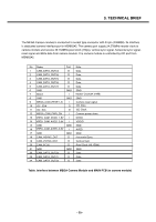
Table. Interface between VGA Camera Module and MAIN PCB in camera module
 |
View all LG KU250 manuals
Add to My Manuals
Save this manual to your list of manuals |
Page 59 highlights
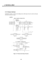
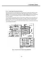
3. TECHNICAL BRIEF The VGA Camera module is connected to socket type connector with 20 pin (CLE9120-2761E). Its interface is dedicated camera interface port in MSM6245. The camera port supply 24.576MHz master clock to camera module and receive 12.288MHz pixel clock (15fps), vertical sync signal, horizontal sync signal, reset signal and 8bits data from camera module. The camera module is controlled by I2C port from MSM6245. No Name Port Note 1 VREG_CAM_DVDD_1.8V I DVDD 2 CAM_MCLK I Master Clock(24.576M) 3 GND GND GND 4 CAM_PCLK O Clock for Camera Data Out(12.288M) 5 CAM_DATA(0) O Data 6 CAM_DATA(1) O Data 7 CAM_DATA(2) O Data 8 CAM_DATA(3) O Data 9 CAM_DATA(4) O Data 10 CAM_DATA(5) O Data 11 CAM_DATA(6) O Data 12 CAM_DATA(7) O Data 13 CAM_VSYNC O Vertical Sync 14 CAM_HSYNC O Horizontal Sync 15 GND GND GND 16 I2C_SDA I I2C Data 17 I2C_SCL I I2C Clock 18 VGA_CAM_RESET_N I Camera reset signal 19 VREG_AVDD_2.8V I Camera I/O Power 20 VREG_AVDD_2.8V I Camera I/O Power Table. Interface between VGA Camera Module and MAIN PCB (in camera module) - 60 -
-
 1
1 -
2
-
3
-
4
-
5
-
6
-
7
-
8
-
9
-
10
-
11
-
12
-
13
-
14
-
15
-
16
-
17
-
18
-
19
-
20
-
21
-
22
-
23
-
24
-
25
-
26
-
27
-
28
-
29
-
30
-
31
-
32
-
33
-
34
-
35
-
36
-
37
-
38
-
39
-
40
-
41
-
42
-
43
-
44
-
45
-
46
-
47
-
48
-
49
-
50
-
51
-
52
-
53
-
 54
54 -
 55
55 -
 56
56 -
 57
57 -
 58
58 -
 59
59 -
 60
60 -
 61
61 -
 62
62 -
 63
63 -
 64
64 -
65
-
66
-
67
-
68
-
69
-
70
-
71
-
72
-
73
-
74
-
75
-
76
-
77
-
78
-
79
-
80
-
81
-
82
-
83
-
84
-
85
-
86
-
87
-
88
-
89
-
90
-
91
-
92
-
93
-
94
-
95
-
96
-
97
-
98
-
99
-
100
-
101
-
102
-
103
-
104
-
105
-
106
-
107
-
108
-
109
-
110
-
111
-
112
-
113
-
114
-
115
-
116
-
117
-
118
-
119
-
120
-
121
-
122
-
123
-
124
-
125
-
126
-
127
-
128
-
129
-
130
-
131
-
132
-
133
-
134
-
135
-
136
-
137
-
138
-
139
-
140
-
141
-
142
-
143
-
144
-
145
-
146
-
147
-
148
-
149
-
150
-
151
-
152
-
153
-
154
-
155
-
156
-
157
-
158
-
159
-
160
-
161
-
162
-
163
-
164
-
165
-
166
-
167
-
168
-
169
-
170
-
171
-
172
-
173
-
174
-
175
 |
 |
