LG KU250 Service Manual - Page 19
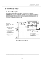
The amplifier outputs drive the RF ports of the quadrature RF-to-baseband downconverters.
 |
View all LG KU250 manuals
Add to My Manuals
Save this manual to your list of manuals |
Page 19 highlights
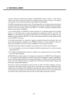
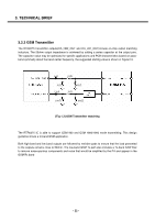
3. TECHNICAL BRIEF The GSM900, DCS, and PCS receiver inputs of RTR6275 are connected directly to the transceiver front-end circuits(filters and antenna switch module). The GSM900, DCS, and PCS receiver inputs use differential configurations to improve common-mode rejection and second-order non-linearity performance. The balance between the complementary signals is critical and must be maintained from the RF filter outputs all the way into the IC pins Since GSM900, DCS, and PCS signals are time-division duplex (the handset can only receive or transmit at one time), switches are used to separate Rx and Tx signals in place of frequency duplexers this is accomplished in the switch module. The GSM900, DCS, and PCS receive signals are routed to the RTR6275 through band selection filters and matching networks that transform single-ended 50-Ω sources to differential impedances optimized for gain and noise figure. The RTR input uses a differential configuration to improve second-order intermodulation and common mode rejection performance. The RTR6275 input stages include MSMcontrolled gain adjustments that maximize receiver dynamic range. The amplifier outputs drive the RF ports of the quadrature RF-to-baseband downconverters. The downconverted baseband outputs are multiplexed and routed to lowpass filters (one I and one Q) having passband and stopband characteristics suitable for GMSK processing. These filter circuits include DC offset corrections. The filter outputs are buffered and passed on to the MSM6245 IC for further processing (an interface shared with the RFR6275 UMTS receiver outputs). - 20 -
-
 1
1 -
2
-
3
-
4
-
5
-
6
-
7
-
8
-
9
-
10
-
11
-
12
-
13
-
 14
14 -
 15
15 -
 16
16 -
 17
17 -
 18
18 -
 19
19 -
 20
20 -
 21
21 -
 22
22 -
 23
23 -
 24
24 -
25
-
26
-
27
-
28
-
29
-
30
-
31
-
32
-
33
-
34
-
35
-
36
-
37
-
38
-
39
-
40
-
41
-
42
-
43
-
44
-
45
-
46
-
47
-
48
-
49
-
50
-
51
-
52
-
53
-
54
-
55
-
56
-
57
-
58
-
59
-
60
-
61
-
62
-
63
-
64
-
65
-
66
-
67
-
68
-
69
-
70
-
71
-
72
-
73
-
74
-
75
-
76
-
77
-
78
-
79
-
80
-
81
-
82
-
83
-
84
-
85
-
86
-
87
-
88
-
89
-
90
-
91
-
92
-
93
-
94
-
95
-
96
-
97
-
98
-
99
-
100
-
101
-
102
-
103
-
104
-
105
-
106
-
107
-
108
-
109
-
110
-
111
-
112
-
113
-
114
-
115
-
116
-
117
-
118
-
119
-
120
-
121
-
122
-
123
-
124
-
125
-
126
-
127
-
128
-
129
-
130
-
131
-
132
-
133
-
134
-
135
-
136
-
137
-
138
-
139
-
140
-
141
-
142
-
143
-
144
-
145
-
146
-
147
-
148
-
149
-
150
-
151
-
152
-
153
-
154
-
155
-
156
-
157
-
158
-
159
-
160
-
161
-
162
-
163
-
164
-
165
-
166
-
167
-
168
-
169
-
170
-
171
-
172
-
173
-
174
-
175
 |
 |
