Lenovo NetVista X40 Quick Reference for NetVista 2179 and 6643 systems (Dutch) - Page 89
Serial connectors, Ethernet connector, Devices & I/O
 |
View all Lenovo NetVista X40 manuals
Add to My Manuals
Save this manual to your list of manuals |
Page 89 highlights
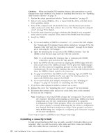
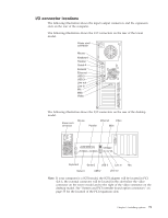
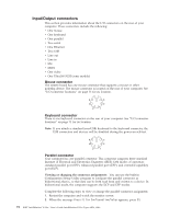
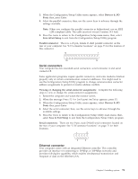
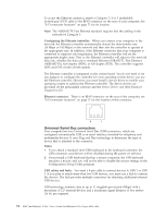
3. When the Configuration/Setup Utility menu appears, select Devices & I/O Ports; then, press Enter. 4. Select the parallel connector; then, use the arrow keys to advance through the settings available. Note: When you configure the parallel connector as bidirectional, use an IEEE 1284-compliant cable. The cable must not exceed 3 meters (9.8 feet). 5. Press Esc twice to return to the Configuration/Setup main menu; then, select Save &Exit Setup to exit from the Configuration/Setup Utility program. Parallel connector: The re is a 25-pin, female D-shell parallel connector on the rear of your computer. See "I/O connector locations" on page 71 for the location of this connector. 13 1 25 14 Serial connectors Your computer has two standard serial connectors: serial connector A and serial connector B. Some application programs require specific connectors, and some modems function properly only at certain communication connector addresses. You might need to use the Configuration/Setup Utility program to change communication connector address assignments to prevent or resolve address conflicts. Viewing or changing the serial-connector assignments: Complete the following steps to view or change the serial-connector assignments. 1. Restart the computer and watch the monitor screen. 2. When the message Press F1 for Configuration/Setup appears, press F1. 3. When the Configuration/Setup Utility menu appears, select Devices & I/O Ports; then, press Enter. 4. Select the serial connector; then, use the arrow keys to advance through the available settings. 5. Press Esc twice to return to the Configuration/Setup Utility main menu; then, select Save & Exit Setup to exit from the Configuration/Setup Utility program. Serial connectors: There are two 9-pin, male D-shell serial connectors located on the rear of your computer. See "I/O connector locations" on page 71 for their locations. 1 5 6 9 Ethernet connector Your computer comes with an integrated Ethernet controller. This controller provides an interface for connecting to 10-Mbps or 100-Mbps networks and provides full-duplex capability, which enables simultaneous transmission and reception of data on the Ethernet LAN. Chapter 5. Installing options 73
-
 1
1 -
2
-
3
-
4
-
5
-
6
-
7
-
8
-
9
-
10
-
11
-
12
-
13
-
14
-
15
-
16
-
17
-
18
-
19
-
20
-
21
-
22
-
23
-
24
-
25
-
26
-
27
-
28
-
29
-
30
-
31
-
32
-
33
-
34
-
35
-
36
-
37
-
38
-
39
-
40
-
41
-
42
-
43
-
44
-
45
-
46
-
47
-
48
-
49
-
50
-
51
-
52
-
53
-
54
-
55
-
56
-
57
-
58
-
59
-
60
-
61
-
62
-
63
-
64
-
65
-
66
-
67
-
68
-
69
-
70
-
71
-
72
-
73
-
74
-
75
-
76
-
77
-
78
-
79
-
80
-
81
-
82
-
83
-
 84
84 -
 85
85 -
 86
86 -
 87
87 -
 88
88 -
 89
89 -
 90
90 -
 91
91 -
 92
92 -
 93
93 -
 94
94 -
95
-
96
-
97
-
98
-
99
-
100
-
101
-
102
-
103
-
104
-
105
-
106
-
107
-
108
-
109
-
110
-
111
-
112
-
113
-
114
-
115
-
116
-
117
-
118
-
119
-
120
-
121
-
122
-
123
-
124
-
125
-
126
-
127
-
128
-
129
-
130
-
131
-
132
-
133
-
134
-
135
-
136
-
137
-
138
-
139
-
140
-
141
-
142
-
143
-
144
-
145
-
146
-
147
-
148
-
149
-
150
-
151
-
152
-
153
-
154
-
155
-
156
 |
 |
