Lenovo ThinkCentre Edge 91 (English) User Guide - Page 61
Pivot the drive bay assembly upward. Then, pivot the two plastic retaining clips outward to remove
 |
View all Lenovo ThinkCentre Edge 91 manuals
Add to My Manuals
Save this manual to your list of manuals |
Page 61 highlights
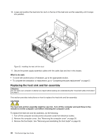
56 78 34 4. Pivot the drive bay assembly upward. Then, pivot the two plastic retaining clips outward to remove the heat sink fan duct from the failing heat sink and fan assembly. Figure 34. Removing the heat sink fan duct 5. Disconnect the heat sink and fan assembly cable from the microprocessor fan connector on the system board. See "Locating parts on the system board" on page 12. Chapter 5. Installing or replacing hardware 49
-
 1
1 -
2
-
3
-
4
-
5
-
6
-
7
-
8
-
9
-
10
-
11
-
12
-
13
-
14
-
15
-
16
-
17
-
18
-
19
-
20
-
21
-
22
-
23
-
24
-
25
-
26
-
27
-
28
-
29
-
30
-
31
-
32
-
33
-
34
-
35
-
36
-
37
-
38
-
39
-
40
-
41
-
42
-
43
-
44
-
45
-
46
-
47
-
48
-
49
-
50
-
51
-
52
-
53
-
54
-
55
-
 56
56 -
 57
57 -
 58
58 -
 59
59 -
 60
60 -
 61
61 -
 62
62 -
 63
63 -
 64
64 -
 65
65 -
 66
66 -
67
-
68
-
69
-
70
-
71
-
72
-
73
-
74
-
75
-
76
-
77
-
78
-
79
-
80
-
81
-
82
-
83
-
84
-
85
-
86
-
87
-
88
-
89
-
90
-
91
-
92
-
93
-
94
-
95
-
96
-
97
-
98
-
99
-
100
-
101
-
102
-
103
-
104
-
105
-
106
-
107
-
108
-
109
-
110
-
111
-
112
-
113
-
114
-
115
-
116
-
117
-
118
-
119
-
120
-
121
-
122
-
123
-
124
-
125
-
126
-
127
-
128
-
129
-
130
-
131
-
132
 |
 |

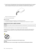
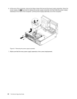
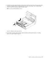
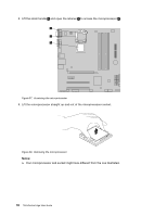
4. Pivot the drive bay assembly upward. Then, pivot the two plastic retaining clips outward to remove
the heat sink fan duct from the failing heat sink and fan assembly.
Figure 34. Removing the heat sink fan duct
5. Disconnect the heat sink and fan assembly cable from the microprocessor fan connector on the system
board. See “Locating parts on the system board” on page 12.
Chapter 5
.
Installing or replacing hardware
49