Lenovo ThinkCentre M55e User Manual - Page 47
CMOS/Recovery
 |
View all Lenovo ThinkCentre M55e manuals
Add to My Manuals
Save this manual to your list of manuals |
Page 47 highlights
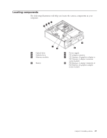
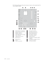
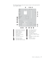
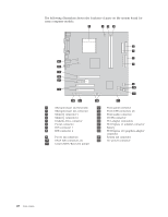
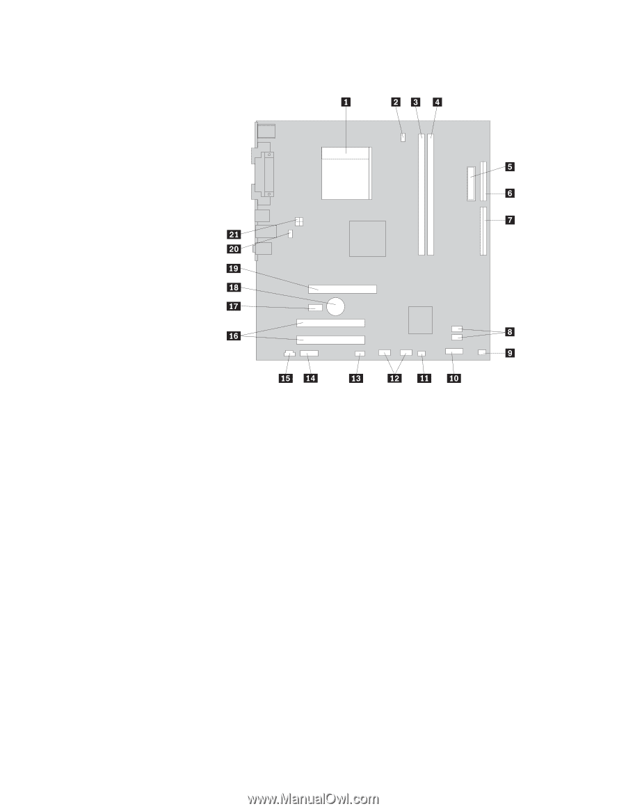
The following illustration shows the locations of parts on the system board for some computer models. 1 Microprocessor and heat sink 12 Front USB connectors (2) 2 Microprocessor fan connector 13 Serial (COM) connector 3 Memory connector 1 14 Front audio connector 4 Memory connector 2 15 CD-IN connector 5 Power connector 16 PCI adapter connectors (2) 6 Diskette drive connector 17 PCI Express x1 adapter connector 7 IDE connector 18 Battery 8 SATA IDE connectors (2) 19 PCI Express x16 graphics adapter connector 9 Power fan connector 20 System fan connector 10 Front panel connector 21 12v power connector 11 Clear CMOS/Recovery jumper Chapter 3. Installing options 27
-
 1
1 -
2
-
3
-
4
-
5
-
6
-
7
-
8
-
9
-
10
-
11
-
12
-
13
-
14
-
15
-
16
-
17
-
18
-
19
-
20
-
21
-
22
-
23
-
24
-
25
-
26
-
27
-
28
-
29
-
30
-
31
-
32
-
33
-
34
-
35
-
36
-
37
-
38
-
39
-
40
-
41
-
 42
42 -
 43
43 -
 44
44 -
 45
45 -
 46
46 -
 47
47 -
 48
48 -
 49
49 -
 50
50 -
 51
51 -
 52
52 -
53
-
54
-
55
-
56
-
57
-
58
-
59
-
60
-
61
-
62
-
63
-
64
-
65
-
66
-
67
-
68
-
69
-
70
-
71
-
72
-
73
-
74
-
75
-
76
-
77
-
78
-
79
-
80
-
81
-
82
-
83
-
84
-
85
-
86
-
87
-
88
-
89
-
90
-
91
-
92
-
93
-
94
-
95
-
96
-
97
-
98
 |
 |
The
following
illustration
shows
the
locations
of
parts
on
the
system
board
for
some
computer
models.
±1²
Microprocessor
and
heat
sink
±12²
Front
USB
connectors
(2)
±2²
Microprocessor
fan
connector
±13²
Serial
(COM)
connector
±3²
Memory
connector
1
±14²
Front
audio
connector
±4²
Memory
connector
2
±15²
CD-IN
connector
±5²
Power
connector
±16²
PCI
adapter
connectors
(2)
±6²
Diskette
drive
connector
±17²
PCI
Express
x1
adapter
connector
±7²
IDE
connector
±18²
Battery
±8²
SATA
IDE
connectors
(2)
±19²
PCI
Express
x16
graphics
adapter
connector
±9²
Power
fan
connector
±20²
System
fan
connector
±10²
Front
panel
connector
±21²
12v
power
connector
±11²
Clear
CMOS/Recovery
jumper
Chapter
3.
Installing
options
27