Lenovo ThinkCentre M55e User Manual - Page 53
Installing, drive
 |
View all Lenovo ThinkCentre M55e manuals
Add to My Manuals
Save this manual to your list of manuals |
Page 53 highlights
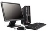
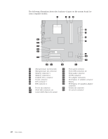
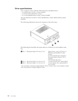
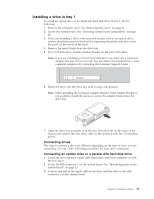
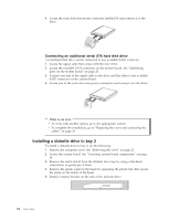
Installing a drive in bay 1 To install an optical drive or an additional hard disk drive in bay 1, do the following: 1. Remove the computer cover. See "Removing the cover" on page 22. 2. Access the system board. See "Accessing system board components" on page 24. 3. If you are installing a drive with accessible media, such as an optical drive, remove the plastic panel in the bezel by squeezing the plastic tabs that secure the panel on the inside of the bezel. 4. Remove the metal shield from the drive bay. 5. For a 5.25-inch drive, install a retainer bracket on the side of the drive. Note: If you are installing a 3.5-inch hard disk drive you must use a Universal Adapter Bracket, 5.25 to 3.5-inch. You can obtain this bracket from a local computer retailer or by contacting the Customer Support Center. 6. Install the drive into the drive bay until it snaps into position. Note: When installing the Universal Adapter Bracket, if the retainer bracket is not available, install the screws to secure the adapter bracket into the drive bay. 7. Align the drive bay assembly with the two slots and rails on the sides of the chassis and connect the new drive cable on the system board. See "Connecting drives." Connecting drives The steps to connect a drive are different depending on the type of drive you are connecting. Use one of the following procedures for your drive connection. Connecting an optical drive or a parallel ATA hard disk drive 1. Locate the two-connector signal cable that comes with your computer or with the new drive. 2. Locate the IDE connector 1 on the system board. See "Identifying parts on the system board" on page 25. 3. Connect one end of the signal cable to the drive and the other to the IDE connector 1 on the system board. Chapter 3. Installing options 33
-
 1
1 -
2
-
3
-
4
-
5
-
6
-
7
-
8
-
9
-
10
-
11
-
12
-
13
-
14
-
15
-
16
-
17
-
18
-
19
-
20
-
21
-
22
-
23
-
24
-
25
-
26
-
27
-
28
-
29
-
30
-
31
-
32
-
33
-
34
-
35
-
36
-
37
-
38
-
39
-
40
-
41
-
42
-
43
-
44
-
45
-
46
-
47
-
 48
48 -
 49
49 -
 50
50 -
 51
51 -
 52
52 -
 53
53 -
 54
54 -
 55
55 -
 56
56 -
 57
57 -
 58
58 -
59
-
60
-
61
-
62
-
63
-
64
-
65
-
66
-
67
-
68
-
69
-
70
-
71
-
72
-
73
-
74
-
75
-
76
-
77
-
78
-
79
-
80
-
81
-
82
-
83
-
84
-
85
-
86
-
87
-
88
-
89
-
90
-
91
-
92
-
93
-
94
-
95
-
96
-
97
-
98
 |
 |