Lenovo ThinkPad Edge 11 Hardware Maintenance Manual - Page 91
Table 28. Removal steps of antenna kit and LCD rear cover assembly, When installing
 |
View all Lenovo ThinkPad Edge 11 manuals
Add to My Manuals
Save this manual to your list of manuals |
Page 91 highlights
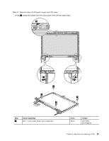
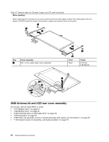
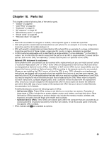
Table 28. Removal steps of antenna kit and LCD rear cover assembly 1 4 3 1 3 2 2 4 When installing: When you install the antenna kit, route the cables as shown in the figures below. As you route the cables, make sure that they are not subjected to any tension. Tension could cause the cables to be damaged by the cable guides, or a wire to be broken. a : Wireless LAN AUX antenna (black) and wireless WAN AUX antenna (blue) b : Wireless LAN MAIN antenna (gray) and wireless WAN MAIN antenna (red) a b Chapter 8. Removing and replacing a FRU 85
-
 1
1 -
2
-
3
-
4
-
5
-
6
-
7
-
8
-
9
-
10
-
11
-
12
-
13
-
14
-
15
-
16
-
17
-
18
-
19
-
20
-
21
-
22
-
23
-
24
-
25
-
26
-
27
-
28
-
29
-
30
-
31
-
32
-
33
-
34
-
35
-
36
-
37
-
38
-
39
-
40
-
41
-
42
-
43
-
44
-
45
-
46
-
47
-
48
-
49
-
50
-
51
-
52
-
53
-
54
-
55
-
56
-
57
-
58
-
59
-
60
-
61
-
62
-
63
-
64
-
65
-
66
-
67
-
68
-
69
-
70
-
71
-
72
-
73
-
74
-
75
-
76
-
77
-
78
-
79
-
80
-
81
-
82
-
83
-
84
-
85
-
 86
86 -
 87
87 -
 88
88 -
 89
89 -
 90
90 -
 91
91 -
 92
92 -
 93
93 -
 94
94 -
 95
95 -
 96
96 -
97
-
98
-
99
-
100
-
101
-
102
-
103
-
104
-
105
-
106
-
107
-
108
-
109
-
110
-
111
-
112
 |
 |
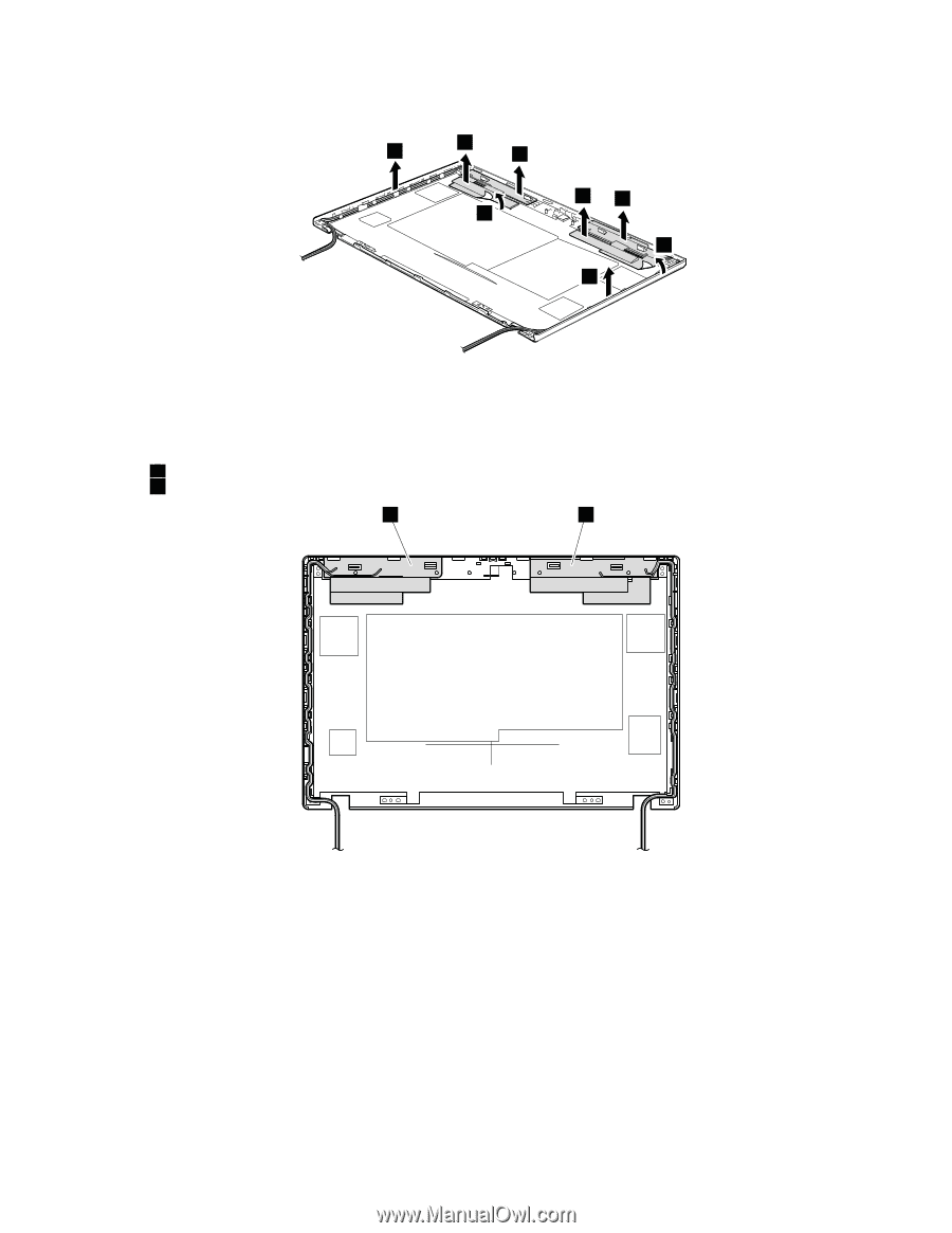
Table 28. Removal steps of antenna kit and LCD rear cover assembly
1
1
2
2
3
3
4
4
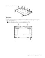
When installing:
When you install the antenna kit, route the cables as shown in the figures below. As you route the cables, make
sure that they are not subjected to any tension. Tension could cause the cables to be damaged by the cable
guides, or a wire to be broken.
a
: Wireless LAN AUX antenna (black) and wireless WAN AUX antenna (blue)
b
: Wireless LAN MAIN antenna (gray) and wireless WAN MAIN antenna (red)
a
b
Chapter 8
.
Removing and replacing a FRU
85