Lexmark Forms Printer 2581 Technical Reference - Page 52
Graphics Commands, Normal Density Bit Image Graphics (60 dpi), Graphics
 |
View all Lexmark Forms Printer 2581 manuals
Add to My Manuals
Save this manual to your list of manuals |
Page 52 highlights
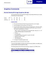
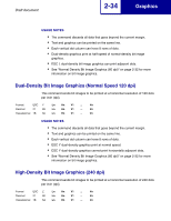
Draft document 2-32 Graphics Graphics Commands Normal Density Bit Image Graphics (60 dpi) This command sends normal density bit images to be printed at 60 dots per inch (dpi) horizontally and 72 dpi vertically. Format ESC K Ln Hn V1 ... Vn Decimal 27 75 Ln Hn V1 ... Vn Hexadecimal 1B 4B Ln Hn V1 ... Vn USAGE NOTES • The command discards all data that goes beyond the current margin. • Text and graphics can be printed on the same line. • Count the total number of bytes of binary bit-image data (A). The total number of bytes cannot exceed the number of dot columns that remain on the line. This value is represented by Ln and Hn. - When a value is represented by two parameter bytes, value (A) = Ln + Hn X 256. Calculate values of A less than 256. • Hn is 0. • Ln is the value. - To calculate values of A equal to or greater than 255. • Divide the value A by 256. • The result is Hn. • The remainder is Ln. • V1 though Vn represent graphics data. Each vertical dot column can have 8 rows of dots. To print bit image graphics, the printer uses either the first 8 (258x) or 20 (259x) wires of the printhead to map the eight bits of data. The following table shows how the print wires are mapped for the 258X printers. Table 2-14: Print Wire Mapping (258X only) Dot Position Top Bit Number Decimal Hexadecimal
-
 1
1 -
2
-
3
-
4
-
5
-
6
-
7
-
8
-
9
-
10
-
11
-
12
-
13
-
14
-
15
-
16
-
17
-
18
-
19
-
20
-
21
-
22
-
23
-
24
-
25
-
26
-
27
-
28
-
29
-
30
-
31
-
32
-
33
-
34
-
35
-
36
-
37
-
38
-
39
-
40
-
41
-
42
-
43
-
44
-
45
-
46
-
 47
47 -
 48
48 -
 49
49 -
 50
50 -
 51
51 -
 52
52 -
 53
53 -
 54
54 -
 55
55 -
 56
56 -
 57
57 -
58
-
59
-
60
-
61
-
62
-
63
-
64
-
65
-
66
-
67
-
68
-
69
-
70
-
71
-
72
-
73
-
74
-
75
-
76
-
77
-
78
-
79
-
80
-
81
-
82
-
83
-
84
-
85
-
86
-
87
-
88
-
89
-
90
-
91
-
92
-
93
-
94
-
95
-
96
-
97
-
98
-
99
-
100
-
101
-
102
-
103
-
104
-
105
-
106
-
107
-
108
-
109
-
110
-
111
-
112
-
113
-
114
-
115
-
116
-
117
-
118
-
119
-
120
 |
 |
