Lexmark Forms Printer 2581 Technical Reference - Page 56
Set Graphics Line Spacing (n/216
 |
View all Lexmark Forms Printer 2581 manuals
Add to My Manuals
Save this manual to your list of manuals |
Page 56 highlights
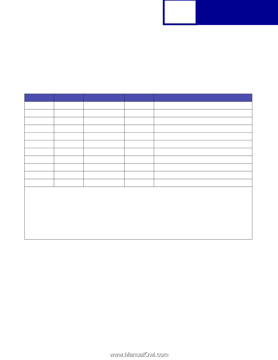
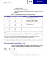
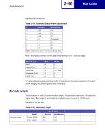
Draft document 2-36 Graphics • The remainder is Ln. • V1 though Vn represent graphics data. • m is a one-byte value to select the graphics mode. The following modes are supported: Table 2-16: High Resolution Graphics m parameter values Decimal Hexadecimal Horizontal Density Wire Comments 0 00 60 8 Same as ESC K graphics command 1 01 120 8 Same as ESC L graphics command 2 02 120 8 Same as ESC Y graphics command 3 03 240 8 Same as ESC Y graphics command 8 08 60 24 High resolution for ESC K 9 09 120 24 High resolution for ESC L 11 0B 180 24 12 0C 360 24 13 0D 120 48 14 0E 180 48 16 10 360 48 Note: The graphics data is organized by byte. For 8-wire modes, it is arranged and mapped to the wires identically to ESC K. For 24-wire modes, the data has three bytes per slice, with the most significant bit of he first byte mapping to the top wire and the least significant bit to of the third byte mapping to the bottom wire. The slices are in sequence from left to right. Modes 2,3 and 12 use consecutive dot elimination. No two adjacent horizontal dots can be printed. The second is eliminated. For high resolution mode (8,9,11 and 12), the count should be: 1+(3 number of slices). For 48-wire modes, the data has six bytes per slice. However the 48-wire image is mapped to the 24-wire head by ORing bits 1 and 2 to wire 1, bit 3 and 4 to wire 2, and so on. Set Graphics Line Spacing (n/216") This command sets line spacing to n/216 inches. It does not cause the form to move. It changes the vertical distance moved when a line feed command is received. Format ESC 3 n Decimal 27 51 n Hexadecimal 1B 33 n USAGE NOTES • The value of n can be from 1 to 255 (decimal), 01 to FF (hexadecimal).
-
 1
1 -
2
-
3
-
4
-
5
-
6
-
7
-
8
-
9
-
10
-
11
-
12
-
13
-
14
-
15
-
16
-
17
-
18
-
19
-
20
-
21
-
22
-
23
-
24
-
25
-
26
-
27
-
28
-
29
-
30
-
31
-
32
-
33
-
34
-
35
-
36
-
37
-
38
-
39
-
40
-
41
-
42
-
43
-
44
-
45
-
46
-
47
-
48
-
49
-
50
-
 51
51 -
 52
52 -
 53
53 -
 54
54 -
 55
55 -
 56
56 -
 57
57 -
 58
58 -
 59
59 -
 60
60 -
 61
61 -
62
-
63
-
64
-
65
-
66
-
67
-
68
-
69
-
70
-
71
-
72
-
73
-
74
-
75
-
76
-
77
-
78
-
79
-
80
-
81
-
82
-
83
-
84
-
85
-
86
-
87
-
88
-
89
-
90
-
91
-
92
-
93
-
94
-
95
-
96
-
97
-
98
-
99
-
100
-
101
-
102
-
103
-
104
-
105
-
106
-
107
-
108
-
109
-
110
-
111
-
112
-
113
-
114
-
115
-
116
-
117
-
118
-
119
-
120
 |
 |