Lexmark Forms Printer 2581 Technical Reference - Page 53
Dual-Density Bit Image Graphics (Half Speed 120 dpi)
 |
View all Lexmark Forms Printer 2581 manuals
Add to My Manuals
Save this manual to your list of manuals |
Page 53 highlights
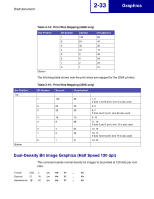
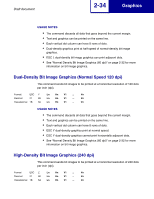
Draft document 2-33 Graphics Dot Position Top Bottom Table 2-14: Print Wire Mapping (258X only) Dot Position Bottom Bit Number 7 6 5 4 3 2 1 0 Decimal 128 64 32 16 8 4 2 1 Hexadecimal 80 40 20 10 08 04 02 01 The following table shows how the print wires are mapped for the 259X printers. Table 2-15: Print Wire Mapping (259X only) Bit Number Decimal Hexadecimal 7 128 80 1, 2 If dots 7 and 6 print, wire 3 is also used. 6 64 40 4, 5 5 32 20 6, 7 If dots 5and 4 print, wire 8is also used. 4 16 10 9, 10 3 8 08 11, 12 If dots 3 and 2 print, wire 13 is also used. 2 4 04 14, 15 1 2 02 16, 17 If dots 1and 0 print, wire 18 is also used. 0 1 01 19. 20 Dual-Density Bit Image Graphics (Half Speed 120 dpi) This command sends normal density bit images to be printed at 120 dots per inch (dpi). Format ESC L Ln Hn V1 ... Vn Decimal 27 76 Ln Hn V1 ... Vn Hexadecimal 1B 4C Ln Hn V1 ... Vn
-
 1
1 -
2
-
3
-
4
-
5
-
6
-
7
-
8
-
9
-
10
-
11
-
12
-
13
-
14
-
15
-
16
-
17
-
18
-
19
-
20
-
21
-
22
-
23
-
24
-
25
-
26
-
27
-
28
-
29
-
30
-
31
-
32
-
33
-
34
-
35
-
36
-
37
-
38
-
39
-
40
-
41
-
42
-
43
-
44
-
45
-
46
-
47
-
 48
48 -
 49
49 -
 50
50 -
 51
51 -
 52
52 -
 53
53 -
 54
54 -
 55
55 -
 56
56 -
 57
57 -
 58
58 -
59
-
60
-
61
-
62
-
63
-
64
-
65
-
66
-
67
-
68
-
69
-
70
-
71
-
72
-
73
-
74
-
75
-
76
-
77
-
78
-
79
-
80
-
81
-
82
-
83
-
84
-
85
-
86
-
87
-
88
-
89
-
90
-
91
-
92
-
93
-
94
-
95
-
96
-
97
-
98
-
99
-
100
-
101
-
102
-
103
-
104
-
105
-
106
-
107
-
108
-
109
-
110
-
111
-
112
-
113
-
114
-
115
-
116
-
117
-
118
-
119
-
120
 |
 |