LiftMaster HDSW24UL Installation Manual - English
LiftMaster HDSW24UL Manual
 |
View all LiftMaster HDSW24UL manuals
Add to My Manuals
Save this manual to your list of manuals |
LiftMaster HDSW24UL manual content summary:
- LiftMaster HDSW24UL | Installation Manual - English - Page 1
, III and IV vehicular swing gate applications. • Visit LiftMaster.com to locate a professional installing dealer in your area. • This gate operator is compatible with myQ® and Security+ 2.0® accessories. Access installation and technical support guides or register this product 1. Take a photo of - LiftMaster HDSW24UL | Installation Manual - English - Page 2
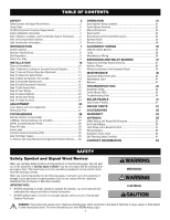
Instructions 40 Maintenance Chart 41 Batteries 41 TROUBLESHOOTING 42 Diagnostic Codes 42 Control Board LEDs 43 Troubleshooting install, operate or maintain the operator, you must read and fully understand this manual and follow all safety instructions. • DO NOT attempt repair or service - LiftMaster HDSW24UL | Installation Manual - English - Page 3
by or intended to service the general public. Class protection devices installed in either the LiftMaster monitored external photoelectric sensors, see page 52 for acceptable sensors. • LiftMaster monitored external edge sensors, see page 52 for acceptable sensors. IMPORTANT SAFETY INSTRUCTIONS - LiftMaster HDSW24UL | Installation Manual - English - Page 4
or obstruction exists, such as the perimeter reachable by a moving gate or barrier. • Instructional and Precautionary Signage 12. For a gate operator utilizing a contact sensor such as an edge sensor: 4. Install the gate operator only when: a. One or more contact sensors shall be located where - LiftMaster HDSW24UL | Installation Manual - English - Page 5
/end users/general contractors, including how to turn off power and how to operate the manual disconnect feature. • Leave safety instructions, product literature, installation manual and maintenance manual with end user. • Explain to the owners the importance of testing by a trained gate system - LiftMaster HDSW24UL | Installation Manual - English - Page 6
45 degrees from the vertical plane, when a 3.1.1 Gates shall be designed, constructed and installed so as not to create an entrapment zone between the gate and the supporting gate is detached from the supporting hardware. structure or other fixed object when the gate moves toward the fully open - LiftMaster HDSW24UL | Installation Manual - English - Page 7
Carton Inventory NOT SHOWN: Documentation packet and hardware bag MONITORED ENTRAPMENT PROTECTION DEVICE Standard Arm Assembly Cover Operator LiftMaster Monitored Retro-Reflective Photoelectric Sensor Model LMRRUL Warning Signs (2) Installation Manual Key (2) Battery 12 Vdc 7AH (2) 7 - LiftMaster HDSW24UL | Installation Manual - English - Page 8
20 ft. - 1,800 lbs. 22 ft. - 1,500 lbs. To optimize performance and extend operator life, the long arm kit model HDLGARM is recommended when installing with gates 16 ft. or longer. See Accessories page 53. When HDLGARM is used, operator has the following maximum gate weight/length: 14 ft. - 4,500 - LiftMaster HDSW24UL | Installation Manual - English - Page 9
vehicles 14 feet (4.27 m) or longer. Vehicle loops are not required but are recommended. Before installing your Access Control Device(s) be sure to complete a site survey and determine the best device for hit or drag across ground Gate MUST swing freely and be supported entirely by its hinges. 9 - LiftMaster HDSW24UL | Installation Manual - English - Page 10
INSTALLATION Types of Installations Standard Installation The illustration is an example of a standard installation. Inside Property 10 - LiftMaster HDSW24UL | Installation Manual - English - Page 11
. To optimize performance and extend operator life, the long arm kit model HDLGARM is recommended when installing with gates 16 ft. or longer. Follow the installation instructions included with the kit. See Accessories page 53. The illustration below shows the recommended dimensions for a standard - LiftMaster HDSW24UL | Installation Manual - English - Page 12
INSTALLATION Chart Installation Refer to the illustration to determine the measurements and location of the concrete pad. Gate Hinge Center Outside A NOTE: There should only be a maximum of F 4" ( - LiftMaster HDSW24UL | Installation Manual - English - Page 13
Step 2 Concrete Pad and Operator Attachment CHECK the national and local building codes before installation. NOTE: When lifting the operator use the handle to avoid damaging the operator 1. Install the electrical conduit. 2. Pour a concrete pad (reinforced concrete is recommended). The concrete pad - LiftMaster HDSW24UL | Installation Manual - English - Page 14
INSTALLATION Step 3 Position the Gate Bracket NOTE: It may be necessary to attach so that the pin slides into the slot. 2. Measure 46" (116.8 cm) or Distance A if using the chart installation, along the gate length from the gate hinge center. 3. Measure 27.5" (69.9 cm) up from the concrete pad - LiftMaster HDSW24UL | Installation Manual - English - Page 15
INSTALLATION Step 5 Secure the Operator Arm Once the operator arm measurements are verified: 1. Weld the gate bracket to the gate. 2. Weld the short ° position). 5. Tighten the handle by pushing it down. Test to make sure the operator arm does not slip on the output shaft. Manual release handle 15 - LiftMaster HDSW24UL | Installation Manual - English - Page 16
3. Test ALL entrapment protection devices AFTER installing the operator, refer to the manual provided with your entrapment protection device. is clearly designated. Illustrations provided by DASMA Gate Systems Safety Guide Edge sensor Entrapment zone Cross Section Secure Side Reflector for - LiftMaster HDSW24UL | Installation Manual - English - Page 17
INSTALLATION Wire Entrapment Protection Devices There are three options for wiring external entrapment protection devices depending on the specific device and how the device will function. Refer to the manual included with your entrapment protection device for more information. These entrapment - LiftMaster HDSW24UL | Installation Manual - English - Page 18
short, break it, or destroy its integrity, replace it with a single wire length. 1. Install the earth ground rod within 3 feet (.9 m) of the operator. 2. Run wire from cleared and secured, at that time the unit may be returned to service. • ALL power wiring should be on a dedicated circuit and well - LiftMaster HDSW24UL | Installation Manual - English - Page 19
INSTALLATION All control wiring used to connect external devices to Class 2 circuits of the operator must be (QPTZ) Power-Limited Circuit Cables, Type CL2, CL2P, CL2R, - LiftMaster HDSW24UL | Installation Manual - English - Page 20
INSTALLATION Plug In Transformer Power Wire plug in transformer power as shown. Control Board Set switch to WALL XFMR Plug in transformer AC Power Switch The - LiftMaster HDSW24UL | Installation Manual - English - Page 21
INSTALLATION 33AH Batteries The batteries are charged in the circuit by the integrated transformer. restore AC power. 33AH batteries are NOT compatible if transformer kit model 3PHCONV is installed. Red Wires Jumper Black Wires Red and Black Wires Harness Kit Model K42-0102-000 Battery Wiring 21 - LiftMaster HDSW24UL | Installation Manual - English - Page 22
INSTALLATION Step 10 Dual Gate setup There are two options for dual gate communication: wired or wireless. Follow the directions according to your application. Do not - LiftMaster HDSW24UL | Installation Manual - English - Page 23
INSTALLATION Wired setup Before digging, contact local underground utility locating companies. Use PVC conduit to prevent damage to cables. 1. Disconnect ALL power to the operator and - LiftMaster HDSW24UL | Installation Manual - English - Page 24
Step 11 Install the Cover Before installing the cover, follow the instructions in the Adjustment section to Manual Disconnect Handle Step 12 Install Warning Signs Installers MUST install the UL required warning signs. The signs MUST be installed in plain view on both sides of each gate installed - LiftMaster HDSW24UL | Installation Manual - English - Page 25
STOP. NOTE: The TEST buttons on the control board will not work until the limits have been set and the required entrapment protection devices are installed. Set the Initial Limits, Speed, and Force For dual gate applications the limits will have to be set for each operator. The gate MUST be - LiftMaster HDSW24UL | Installation Manual - English - Page 26
ADJUSTMENT Speed Control The SPEED CONTROL dial controls the speed of the operator. The dial is preset to minimum from the factory. Set the speed as low as possible for the intended application. 90 degree travel time = 13-36 seconds. NOTE: travel time will vary based on arm configuration. See page - LiftMaster HDSW24UL | Installation Manual - English - Page 27
ADJUSTMENT Adjust the Limits After both limits are set and the operator is ready to run, one limit can be adjusted independently from the other by following steps 1-3 of the Initial Limit and Force Adjustment section. After any limit adjustment: 1. Cycle the gate open and close to automatically - LiftMaster HDSW24UL | Installation Manual - English - Page 28
to provide reasonable protection against harmful interference in a residential installation. This equipment generates, uses and can radiate radio frequency energy and, if not installed and used in accordance with the instructions, may cause harmful interference to radio communications. However - LiftMaster HDSW24UL | Installation Manual - English - Page 29
Set up an account and follow the app instructions to add your gate operator. 5. The LiftMaster Internet Gateway will pair to the operator if #1 to the ON position to enter Admin Mode. NOTE: For new installations press the login button without entering information in the Admin Username and Admin - LiftMaster HDSW24UL | Installation Manual - English - Page 30
ONE gate operator (see the KPW5/KPW250 manual for complete programming instructions). The Constant Pressure Override feature is intended are present. External entrapment protection devices include LiftMaster monitored photoelectric sensors and LiftMaster monitored wired and wireless edge sensors. Be - LiftMaster HDSW24UL | Installation Manual - English - Page 31
not running on batteries). Cycle Quantity Feedback Use during servicing only to determine operator cycles. Use during servicing only to determine operator cycles. Use during servicing only to determine operator cycles. Use during servicing only to determine operator cycles. Fire Dept Open Input - LiftMaster HDSW24UL | Installation Manual - English - Page 32
, see Fine Tune the Force page 26. 12 STATUS LEDs: The STATUS LEDs indicate the status of the operator. See Status LED Chart in the Troubleshooting section. 1 2 3 45 6 7 8 9 10 11 12 32 - LiftMaster HDSW24UL | Installation Manual - English - Page 33
Switch The reset switch has the following functions: • Set the switch to the RESET position to disable gate operation. Use this switch before servicing the gate or manually disconnecting the gate. The stop LED will be illuminated. • To hold the gate open, run the gate to the open position and then - LiftMaster HDSW24UL | Installation Manual - English - Page 34
up to 5 minutes and the operator will need to be reset. A. The gate is hitting an obstruction. B. The operator arm or gate is incorrectly installed. C. The gate does not meet specifications. C D D. Gate hinges are too tight or broken and the gate is not moving freely. E. The gate is moving - LiftMaster HDSW24UL | Installation Manual - English - Page 35
ACCESSORY WIRING All control wiring used to connect external devices to Class 2 circuits of the operator must be (QPTZ) Power-Limited Circuit Cables, Type CL2, CL2P, CL2R, or CL2X or other cable with equivalent or better electrical, mechanical, and flammability ratings. External Control Devices - LiftMaster HDSW24UL | Installation Manual - English - Page 36
ACCESSORY WIRING Locks Maglock (2 Terminals, N.C. and COM) Relay contact output, Normally - closed (N.C.) output for maglocks. Relay activates prior to motor activation and during motor run. Relay is off when motor is off. CONTROL BOARD MAGLOCK NOT PROVIDED Miscellaneous Wiring Three button - LiftMaster HDSW24UL | Installation Manual - English - Page 37
is faulted and inoperative). Communication bus connects control board, expansion board, or relay 4. ANTI-TAIL switch: adapter board. Also connects LiftMaster wireless edge device LMWEKITU. OFF: When CLOSE EYES/Interrupt loop is activated it causes a closing gate to stop and reverse. 9. Input - LiftMaster HDSW24UL | Installation Manual - English - Page 38
AC shutdown. shutdown. ON OFF ON Energizes if gate is manually tampered with by being pushed off of close limit. For an ,000.). Cycle count displayed is between 1,000 and 9,999,000 cycles. After servicing, set Aux Relay switches back to their appropriate positions. Cycle count cannot be reset - LiftMaster HDSW24UL | Installation Manual - English - Page 39
EXPANSION AND RELAY ADAPTER BOARDS Wiring Accessories to the Expansion Board Refer to the chart below and the corresponding image for a description of the expansion board inputs. 1 Wireless edge, control board, or Connection for wireless edge receiver, control board or relay adapter board. relay - LiftMaster HDSW24UL | Installation Manual - English - Page 40
moving. • KEEP GATES PROPERLY MAINTAINED. Read this manual carefully. Have a qualified service person make repairs to gate hardware. • ALL maintenance or INJURY to persons use ONLY LiftMaster part 29-NP712 for replacement batteries. • SAVE THESE INSTRUCTIONS. • ALWAYS wear protective gloves and - LiftMaster HDSW24UL | Installation Manual - English - Page 41
servicing. DESCRIPTION TASK CHECK AT LEAST ONCE EVERY Entrapment Protection Devices Warning Signs Manual damage Review diagnostic history for identification of intermittent problems Replace MONTH 6 MONTHS 3 YEARS X every 3 years. Use only LiftMaster part 29-NP712 for replacement installed. 41 - LiftMaster HDSW24UL | Installation Manual - English - Page 42
TROUBLESHOOTING To protect against fire and electrocution: • DISCONNECT power (AC or solar and battery) BEFORE installing or servicing operator. For continued protection against fire: • Replace ONLY with fuse of same type and rating. Diagnostic Codes To View the Codes The codes will show - LiftMaster HDSW24UL | Installation Manual - English - Page 43
TROUBLESHOOTING Control Board LEDs INPUT OFF POWER ON STATUS LEDS OFF state AC charger or Solar power available BATT OFF CHARGING ON Not charging Three stage - LiftMaster HDSW24UL | Installation Manual - English - Page 44
TROUBLESHOOTING Troubleshooting Chart SYMPTOM Operator does not run and diagnostic display not to limit. Repair gate as needed. d. Change geometry or allow gate to open further a. Use manual disconnect, manually move gate, and ensure gate moves easily limit to limit. Repair gate as needed. b. Gate - LiftMaster HDSW24UL | Installation Manual - English - Page 45
TROUBLESHOOTING SYMPTOM Gate opens, but will not close with transmitter or Timer-to-Close. Gate closes, but will not open. Exit loop activation does not cause - LiftMaster HDSW24UL | Installation Manual - English - Page 46
TROUBLESHOOTING SYMPTOM Expansion board function not controlling gate. Maglock not working correctly or relay board. a. Add more solar panels b. Reduce the accessory power draw by using LiftMaster low power accessories c. Replace batteries d. Relocate the solar panels away from obstructions (trees, - LiftMaster HDSW24UL | Installation Manual - English - Page 47
given zones as shown on the map below. Local geography and weather conditions may require additional solar panels. Solar powered gate operator installations are not supported in northern climates due to cold weather and a reduced number of hours of sunlight during the winter months. The cycles/day - LiftMaster HDSW24UL | Installation Manual - English - Page 48
Solar usage guide All performance metrics are estimates and are subject to change at any time. Actual results will vary due to variables specific to the site. Typical System Standby Battery Current Consumption (mA) System voltage Main board with no radios programmed One or more LiftMaster® remote - LiftMaster HDSW24UL | Installation Manual - English - Page 49
an 180° additional 15° (solar panel(s) sits more vertical). Installation Solar panel(s) MUST be installed facing south. Use a compass to determine direction. Below are general instructions for installing the solar panel(s). Your installation may vary slightly depending on the solar panel purchased - LiftMaster HDSW24UL | Installation Manual - English - Page 50
SOLAR PANELS Wire the Solar Panels and Batteries 24W min. - 60W max. for solar applications. NOTE: 33AH batteries are strongly recommended for optimal solar performance. 1. Connect (+) wire from solar panels to (+) pin on CHARGE IN connector on control board. 2. Connect (-) wire from solar panels - LiftMaster HDSW24UL | Installation Manual - English - Page 51
Output Shaft Complete K41-0086-000 Motor Drive K41-0095-000 Transformer K41-0067-000 Top (Cludge) Cover K13-36117-1 REPAIR PARTS Output Arm K09-50119 Cludge Assembly K41-0085-000 Motor K41-0082-000 Standard Arm Assembly K41-0138-000 APS encoder with cable K41-0092-000 7AH 12 Vdc Batteries K74- - LiftMaster HDSW24UL | Installation Manual - English - Page 52
-button to 4-button, visor or key chain. The following remote controls are compatible with operators manufactured by LiftMaster after 1993. Contact your authorized LiftMaster dealer for additional details and options. 3-button remote control The 3-button remote control can be programmed to control - LiftMaster HDSW24UL | Installation Manual - English - Page 53
to be remotely installed. Model 86LM Plug-in loop detector Low power. Conveniently plugs into existing control board. Not to be used as entrapment protection. Model LOOPDETLM Loop Detector Low power loop detectors mounted and wired separately inside control box. LiftMaster low power accessory - LiftMaster HDSW24UL | Installation Manual - English - Page 54
this product. Then send this product, pre-paid and insured, to our service center for warranty repair. You will be advised of shipping instructions when you call. Please include a brief description of the problem and a dated proof-of-purchase receipt with any product returned for warranty repair - LiftMaster HDSW24UL | Installation Manual - English - Page 55
APPENDIX SAMS Wiring with Relays Not Energized SAMS Operation To keep vehicles from rushing the gate, the barrier arm stays in closed position until the gate reaches fully open position then the barrier arm is released to open and allow vehicles to pass. AUX Relay 1 55 - LiftMaster HDSW24UL | Installation Manual - English - Page 56
Close: ON Speed Set the speed control dial on each operator to the desired setting, see page 26 for more details Expansion board LiftMaster Internet Gateway Garage and Gate Monitor FEATURE PRIMARY OPERATOR SECONDARY OPERATOR QUICK CLOSE Switch ON OFF ANTI-TAIL Switch ON OFF LOW BATT - LiftMaster HDSW24UL | Installation Manual - English - Page 57
sets the force. When limits are set properly the operator will automatically exit limit setting mode. Refer to the Adjustment section and follow the instructions for Speed Control, Fine Tune the Force, and Obstruction Test. Adjust the limits If the limits have already been set the operator will - LiftMaster HDSW24UL | Installation Manual - English - Page 58
Wiring Diagram APPENDIX To protect against fire and electrocution: • DISCONNECT power (AC or solar and battery) BEFORE installing or servicing operator. For continued protection against fire: • Replace ONLY with fuse of same type and rating. POWER LOCKS GATES PROTECTION LOOPS CONTROLS CONTROL - LiftMaster HDSW24UL | Installation Manual - English - Page 59
the code history and some are not. If a code is not saved it will briefly appear on the display as it occurs, then disappear. LiftMaster System Installed System Informational External Entrapment Protection Inherent Entrapment Protection Code 31 34 35 36 37 38 40 41 42 43 44 45 46 47 48 53 - LiftMaster HDSW24UL | Installation Manual - English - Page 60
and reprogram the two operators. Check the connections between the main board and the expansion board. Non-monitored contact closure devices are not supported. Make sure connected devices are monitored. Check edges for proper orientation and resistive end cap connection. Check for obstruction. If no - LiftMaster HDSW24UL | Installation Manual - English - Page 61
Fail Gates prevented from falling over if disconnected from supporting hardware Pass / Fail SWING Distance from pivot point Installer: Name of Dealership: Phone: Dealership Address (Street Address/City/State/Zip): Dealer Signature: Installer Signature: Customer Signature: © 2019 LiftMaster - LiftMaster HDSW24UL | Installation Manual - English - Page 62
nearest the roadway (such as a gate support post) and the gate frame when the gap must be Interior posts, Guide posts protected. Install safety device to protect entrapment installation possibilities and are for illustration purposes only. See device and operator manuals for complete instruction - LiftMaster HDSW24UL | Installation Manual - English - Page 63
This page intentionally left blank - LiftMaster HDSW24UL | Installation Manual - English - Page 64
Contact Information LiftMaster.com LiftMaster Dealer Extranet: dealer.liftmaster.com/login LiftMaster Training Academy: liftmastertraining.com 800-528-2806 Mon-Fri 5:00 am to 6:00 pm MST 300 Windsor Drive Oak Brook, IL 60523 LiftMaster.com © 2020, The Chamberlain Group, Inc. - All Rights Reserved
-
 1
1 -
 2
2 -
 3
3 -
 4
4 -
 5
5 -
 6
6 -
 7
7 -
8
-
9
-
10
-
11
-
12
-
13
-
14
-
15
-
16
-
17
-
18
-
19
-
20
-
21
-
22
-
23
-
24
-
25
-
26
-
27
-
28
-
29
-
30
-
31
-
32
-
33
-
34
-
35
-
36
-
37
-
38
-
39
-
40
-
41
-
42
-
43
-
44
-
45
-
46
-
47
-
48
-
49
-
50
-
51
-
52
-
53
-
54
-
55
-
56
-
57
-
58
-
59
-
60
-
61
-
62
-
63
-
64
 |
 |
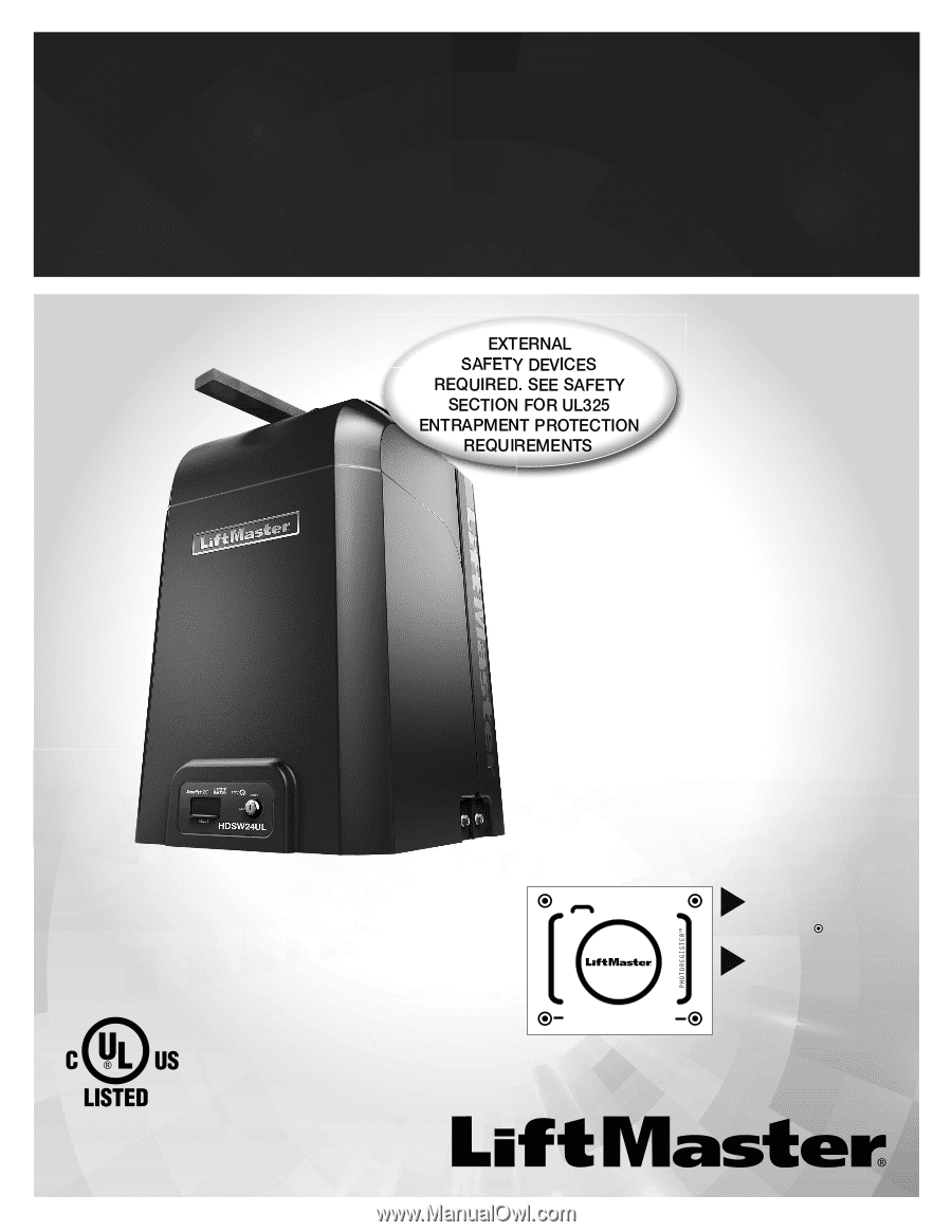
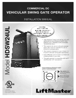
COMMERCIAL DC
VEHICULAR SWING GATE OPERATOR
INSTALLATION MANUAL
LiftMaster
300 Windsor Drive
Oak Brook, IL 60523
•
THIS PRODUCT MUST BE INSTALLED AND
SERVICED IN ACCORDANCE WITH THIS
MANUAL BY A TRAINED GATE SYSTEMS
TECHNICIAN ONLY.
•
This model is for use on vehicular passage
gates ONLY and not intended for use on
pedestrian passage gates.
•
This model is intended for use in Class I, II,
III and IV vehicular swing gate applications.
•
Visit LiftMaster.com to locate a professional
installing dealer in your area.
•
This gate operator is compatible with myQ
®
and Security+ 2.0
®
accessories.
Access installation and technical support
guides or register this product
Send it in
by texting
the photo to 71403.
Take a photo
of the
camera icon including
the points (
).
1.
2.
HDSW24ULTECH
Model
HDSW24UL