LiftMaster SW470 SW490 S3 BOARD Manual - Page 10
Cont'd, System Features, Activity Led, Audible Warning Device - motor
 |
View all LiftMaster SW470 manuals
Add to My Manuals
Save this manual to your list of manuals |
Page 10 highlights
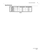
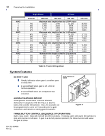
10 Preparing the Installation AWG 6 8 10 12 AWG 6 8 10 12 AWG 6 8 10 12 AWG 6 8 10 12 Single Phase 3 Phase 115 VAC 700 450 275 175 475 300 200 125 325 225 150 100 250 150 100 75 230 VAC 230 VAC 460 VAC Maximum wire length in feet for 1/3 HP motor 3,100 4,750 14,225 1,950 3,000 8,975 1,225 1,900 5,650 775 1,175 3,525 Maximum wire length in feet for ½ HP motors 2,075 2,850 14,225 1,300 1,800 8,975 825 1,125 5,650 525 725 3,525 Maximum wire length in feet for ¾ HP motors 1,250 2,050 7,125 800 1,300 4,500 500 825 2,825 325 525 1,775 Maximum wire length in feet for 1 hp motors 950 1,425 5,700 600 900 3,600 375 575 2,275 250 375 1,425 Table 5: Power Wiring Chart 575 VAC 35,550 22,425 14,075 8,825 17,775 11,225 7,050 4,425 11,850 7,475 4,700 2,950 8,900 5,625 3,525 2, 225 System Features ACTIVITY LED Steady indication when gate is at either open or close limit. 1 second flash when gate is off a limit in normal operation. 2 second flash when an entrapment has occurred. AUDIBLE WARNING DEVICE If the operator should have a second inherent obstruction in sequence with the first; (i.e. back to back), the sounder will activate. Also, the sounder can be programmed to come on 3 seconds prior to gate movement, and remain on during gate movement. Figure 3 0 1 -G 0 6 6 5 F1 5 THREE BUTTON CONTROL (SEQUENCE OF OPERATION) Open, stop, close. Stop will override all other functions. If closing, Open will cause the operator to stop and reverse to full open. If gate is at its fully opened position, the Close function will cause the gate to close. Doc 01-G0665 Rev C
-
 1
1 -
2
-
3
-
4
-
 5
5 -
 6
6 -
 7
7 -
 8
8 -
 9
9 -
 10
10 -
 11
11 -
 12
12 -
 13
13 -
 14
14 -
 15
15 -
16
-
17
-
18
-
19
-
20
-
21
-
22
-
23
-
24
-
25
-
26
-
27
-
28
-
29
-
30
-
31
 |
 |
