LiftMaster SW470 SW490 S3 BOARD Manual - Page 9
Preparing The Installation - weight
 |
View all LiftMaster SW470 manuals
Add to My Manuals
Save this manual to your list of manuals |
Page 9 highlights
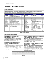
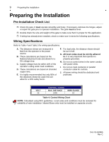
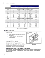
9 Preparing the Installation Preparing the Installation Pre-Installation Check List ! Check the gate. It must operate smoothly and freely. If necessary, lubricate the hinges, adjust or repair the gate prior to operator installation. The gate must be level. ! Double check the size and weight of the gate to make sure that it is proper for this application. ! If wiring has already been installed, check to make sure it meets the following specifications. Wiring Specifications Refer to Table 4 and Table 5 for wiring specifications. A. The distances shown are measured in feet from the operator to the power source. B. These calculations are based on the National Electrical Code and allows for a 5% voltage drop. C. Supply voltage must be within 10% of the operator's rating under load conditions. D. These calculations are based on stranded copper wire. E. It is highly recommended that only 90% of the distances shown be used; this will allow for a 10% safety factor. F. For dual units, the distance shown should be cut in half. G. All local codes must be strictly adhered to. It is very important that operator is properly grounded. H. Do not run control wires in the same conduit with power wires. I. Do not run multi conductor or parallel conductor cable for controls. J. All power wiring should be dedicated and protected. VOLT 24 CONTROL WIRING MAX. DISTANCE 1000 WIRE GUAGE 18 Table 4: Control Wiring Chart NOTE: Calculated using NEC guidelines. Local codes and conditions must be reviewed for suitability of wire installation. Master/Slave units must be installed on separate circuits. Doc 01-G0665 Rev C
-
 1
1 -
2
-
3
-
 4
4 -
 5
5 -
 6
6 -
 7
7 -
 8
8 -
 9
9 -
 10
10 -
 11
11 -
 12
12 -
 13
13 -
 14
14 -
15
-
16
-
17
-
18
-
19
-
20
-
21
-
22
-
23
-
24
-
25
-
26
-
27
-
28
-
29
-
30
-
31
 |
 |