LiftMaster SW470 SW490 S3 BOARD Manual - Page 19
Programming
 |
View all LiftMaster SW470 manuals
Add to My Manuals
Save this manual to your list of manuals |
Page 19 highlights
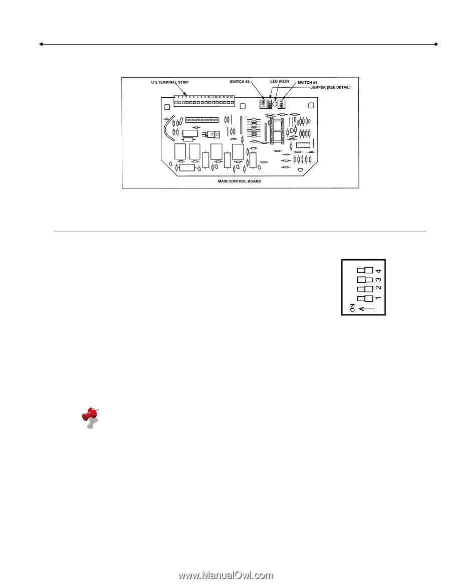
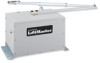
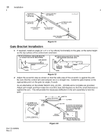
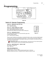
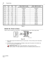
Programming Programming 19 Figure 16 0 1 -G 06 6 5 F1 1 Switch #1: Operator Programming POLE #1 - SINGLE/CLOSE BUTTON ON = Close button only OFF = Open/Close Button POLE #2 - RIGHT HAND/LEFT HAND ON = Left Hand (gate will open to the left) OFF = Right Hand (gate will open to the right) (Determine hand selection from inside of fence looking out) POLE #3 - WARNING DEVICE ON = Warning device will turn on 3 seconds before gate starts to move in either direction. OFF = Warning device disabled. 0 1-0 66 5 F1 2 Figure 17 Timer to close is locked out at the factory, to activate the timer to close, move timer disable jumper from bottom two pins (show illustration) to top two pins. Then set time per the chart on page 20. To lock the timer to close program and disable, simply return the jumper to the bottom two pins, or move all pins of SW#2 to ON. IMPORTANT NOTE: When using master/slave, only set the time for the master operator. The slave operator must be set to disable position (all poles on). POLE #4 - MASTER/SLAVE - SINGLE UNIT ON = Master or single Unit OFF = Slave unit RED LED INFORMATION Continuous ON = Unit is on a limit Blinking 1 flash per second = Normal operation (gate travel or mid-stop) Blinking 2 flashes per second = Entrapment level 1 (operator reverse to limit) Doc 01-G0665 Rev C
-
 1
1 -
2
-
3
-
4
-
5
-
6
-
7
-
8
-
9
-
10
-
11
-
12
-
13
-
 14
14 -
 15
15 -
 16
16 -
 17
17 -
 18
18 -
 19
19 -
 20
20 -
 21
21 -
 22
22 -
 23
23 -
 24
24 -
25
-
26
-
27
-
28
-
29
-
30
-
31
 |
 |