LiftMaster SW470 SW490 S3 BOARD Manual - Page 16
Gate Installation,
 |
View all LiftMaster SW470 manuals
Add to My Manuals
Save this manual to your list of manuals |
Page 16 highlights
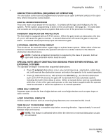
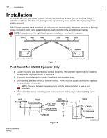
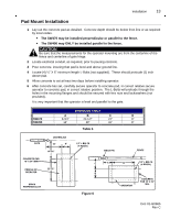
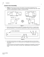
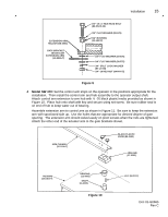
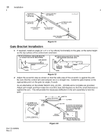
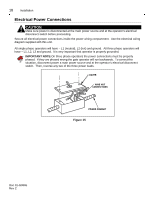
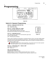
16 Installation SERRATED FLANGE NUT (84-WH-38) SHOULDER BOLT (82-SB50-08) FLAT WASHER (85-FW-38) GATE BRACKET (10-2111) HEX HEAD BOLT (82-HN38-20) EXTENSION ARM (10-2109) ARM CHANNEL (10-2108-T) Figure 11 Gate Bracket Installation 1 If required, install an angle (2" x 2" x ¼" by others) horizontally on the gate, at the same height as the top surface of the control arm extension. 0 1 -G 0 66 5 F6 Figure 12 2 Adjust the eccentric stop as shown so that the wide area of the eccentric is against the arm. Be sure that the control arm and actuator are in a straight line. Install the gate bracket at the appropriate point on the gate (or angle, if used). As an alternative on the Model SW470 only, (2) 3/8 - 16 bolts and a nut plate are provided. Adjust arm length and then rotate the eccentric stop 180 degrees so that the small thickness is against the arm. This will provide the necessary deflection in the arm assembly to lock the gate. 0 1 -G 0 66 5 F8 Doc 01-G0665 Rev C Figure 13
-
 1
1 -
2
-
3
-
4
-
5
-
6
-
7
-
8
-
9
-
10
-
 11
11 -
 12
12 -
 13
13 -
 14
14 -
 15
15 -
 16
16 -
 17
17 -
 18
18 -
 19
19 -
 20
20 -
 21
21 -
22
-
23
-
24
-
25
-
26
-
27
-
28
-
29
-
30
-
31
 |
 |
