LiftMaster SW470 SW490 S3 BOARD Manual - Page 15
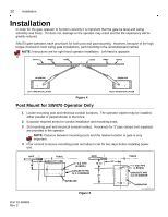
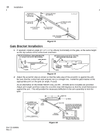
CONT'D, Assemble extension arm to control arm as shown
 |
View all LiftMaster SW470 manuals
Add to My Manuals
Save this manual to your list of manuals |
Page 15 highlights
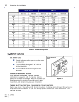
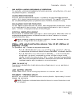
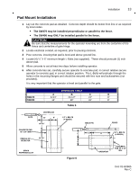
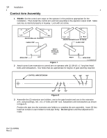
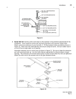
Installation 15 EXTENSION ARM HOLDER (08-2001) GATE BRACKET (W-2001) OR EXTENSION ARM (10-2026-T) 3/4"-10 x 3 HEX HEAD BOLT (82-HN75-28) 3/4" FLAT WASHER (80-575) 3/4" BUSHING (12-10172) 3/4" FLAT WASHER (80-575) 3/4" FLAT WASHER (80-575) 3/4" SPLIT LOCK WASHER (85-LS-38) 3/4"-10 HEX NUT (84-RH-75) Figure 9 0 1 -G 0 66 5 F4 4 Model SW 470: Set the control arm stops on the operator in the positions appropriate for the installation. Then install the control arm and hub assembly to the operator output shaft. Attach control arm extension to arm hub with ¼ -20 black plastic knobs provided as shown in Figure 10. Place hub onto shaft with key and secure using set screw. Be sure rubber seal is on end of hub to keep water out of bearing. Assemble extension arm to control arm as shown in Figure 11. Be sure to keep the extension arm with spot-faced side up. Use the holes that are appropriate for desired degree of gate opening. The extension arm should swivel easily on pivot screws when the nuts are tightened. Attach the other end of the actuator arm to the gate brackets shown. ARM CHANNEL (10-2108-T) BLACK PLASTIC KNOB (80-2103) ARM HUB (07-2101) HOUSING (10-2101-T) BEARING (12-3000) SHAFT (11-2101) Figure 10 KEY (80-2112) 0 1 -G 0 66 5 F5 Doc 01-G0665 Rev C
-
 1
1 -
2
-
3
-
4
-
5
-
6
-
7
-
8
-
9
-
 10
10 -
 11
11 -
 12
12 -
 13
13 -
 14
14 -
 15
15 -
 16
16 -
 17
17 -
 18
18 -
 19
19 -
 20
20 -
21
-
22
-
23
-
24
-
25
-
26
-
27
-
28
-
29
-
30
-
31
 |
 |
