Linksys WRE54G Cisco WAP54GP Wireless-G Exterior Access Point User Guide - Page 19
Connecting the Wireless-G Exterior Access, Point - ip
 |
UPC - 745883559046
View all Linksys WRE54G manuals
Add to My Manuals
Save this manual to your list of manuals |
Page 19 highlights
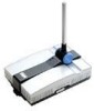
Wireless-G Exterior Access Point Chapter 4: Connecting the Wireless-G Exterior Access Point Overview hardware: the physical aspect of computers, telecommunications, and other information technology devices. This chapter explains how to mount and connect the Access Point. Depending on your application, you might want to set up the IP address of the device first before mounting the device. Refer to "Chapter 5: Setting Up the Wireless-G Exterior Access Point". Hardware Installation 1. Locate an optimum location on a wall for the Access Point. Refer to the antenna pattern in "Chapter 3: Getting to Know the Wireless-G Exterior Access Point" to adjust the angle of the Access Point for your application. 2. Using the mounting plate as a template, mark the locations of the two wall-mount slots that are on the bottom of the mounting plate. Then, install a screw into each location. Figure 4-1: Mark the Locations of the Two Wall-Mount 3. Use four screws (included with the Access Point) to attach the mounting plate to the back panel of the Access Point. 4. Connect the included Category 5e Ethernet network cable to the Ethernet network port of the Access Point. Then, screw the connector cap tightly onto the port, so the Access Point has a water-resistant seal. 5. If you want to connect an optional, high-gain external antenna, unscrew the cap that protects the Type-N antenna port, then, connect your antenna cable to this port. Chapter 4: Connecting the Wireless-G Exterior Access Point Overview Slots 12
-
 1
1 -
2
-
3
-
4
-
5
-
6
-
7
-
8
-
9
-
10
-
11
-
12
-
13
-
 14
14 -
 15
15 -
 16
16 -
 17
17 -
 18
18 -
 19
19 -
 20
20 -
 21
21 -
 22
22 -
 23
23 -
 24
24 -
25
-
26
-
27
-
28
-
29
-
30
-
31
-
32
-
33
-
34
-
35
-
36
-
37
-
38
-
39
-
40
-
41
-
42
-
43
-
44
-
45
-
46
-
47
-
48
-
49
-
50
-
51
-
52
-
53
-
54
-
55
-
56
-
57
-
58
-
59
-
60
-
61
-
62
-
63
-
64
-
65
-
66
-
67
-
68
-
69
-
70
-
71
-
72
-
73
-
74
-
75
-
76
 |
 |
