MSI MS-6580-060 User Guide - Page 32
RJ-45 LAN Jack Optional, VGA Connector
 |
UPC - 816909002959
View all MSI MS-6580-060 manuals
Add to My Manuals
Save this manual to your list of manuals |
Page 32 highlights
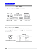
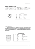
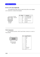
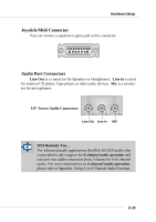
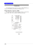
MS-6580 ATX Mainboard RJ-45 LAN Jack (Optional) The mainboard provides a RJ-45 connector that allows your computer to be connected to a network environment. Activity Indicators LAN Jack (RJ-45) Pin Signal 1 TDP 2 TDN 3 RDP 4 NC 5 NC 6 RDN 7 NC 8 NC Description Transmit differential pair Transmit differential pair Receive differential pair Not used Not used Receive differential pair Not used Not used VGA Connector The mainboard provides a DB 15-pin female connector to connect a VGA monitor. 5 1 15 11 VGA Connector (DB 15-pin) Pin Signal Description 1 RED 2 GREEN 3 BLUE 4 N/C 5 GND 6 GND 7 GND 8 GND 9 +5V 10 GND 11 N/C 12 SDA 13 Horizontal Sync 14 Vertical Sync 15 SCL 2-12
-
 1
1 -
2
-
3
-
4
-
5
-
6
-
7
-
8
-
9
-
10
-
11
-
12
-
13
-
14
-
15
-
16
-
17
-
18
-
19
-
20
-
21
-
22
-
23
-
24
-
25
-
26
-
 27
27 -
 28
28 -
 29
29 -
 30
30 -
 31
31 -
 32
32 -
 33
33 -
 34
34 -
 35
35 -
 36
36 -
 37
37 -
38
-
39
-
40
-
41
-
42
-
43
-
44
-
45
-
46
-
47
-
48
-
49
-
50
-
51
-
52
-
53
-
54
-
55
-
56
-
57
-
58
-
59
-
60
-
61
-
62
-
63
-
64
-
65
-
66
-
67
-
68
-
69
-
70
-
71
-
72
-
73
-
74
-
75
-
76
-
77
-
78
-
79
-
80
-
81
-
82
-
83
-
84
-
85
-
86
-
87
-
88
-
89
-
90
-
91
-
92
-
93
-
94
-
95
-
96
-
97
-
98
-
99
-
100
-
101
-
102
-
103
-
104
-
105
-
106
-
107
 |
 |

2-12
MS-6580 ATX Mainboard
RJ-45 LAN Jack (Optional)
The mainboard provides a RJ-45 connector that allows your computer
to be connected to a network environment.
LAN Jack
(RJ-45)
Activity
Indicators
Pin
Signal
Description
1
TDP
Transmit differential pair
2
TDN
Transmit differential pair
3
RDP
Receive differential pair
4
NC
Not used
5
NC
Not used
6
RDN
Receive differential pair
7
NC
Not used
8
NC
Not used
VGA Connector
The mainboard provides a DB 15-pin female connector to connect a
VGA monitor.
5
1
15
11
VGA Connector
(DB 15-pin)
Pin
Signal Description
1
RED
2
GREEN
3
BLUE
4
N/C
5
GND
6
GND
7
GND
8
GND
9
+5V
10
GND
11
N/C
12
SDA
13
Horizontal Sync
14
Vertical Sync
15
SCL