MSI MS-6580-060 User Guide - Page 46
IrDA Infrared Module Header: JIR1, CD-In Connector: CD_IN1
 |
UPC - 816909002959
View all MSI MS-6580-060 manuals
Add to My Manuals
Save this manual to your list of manuals |
Page 46 highlights
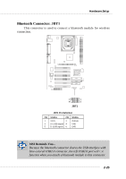
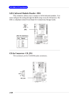
MS-6580 ATX Mainboard IrDA Infrared Module Header: JIR1 This connector allows you to connect to IrDA Infrared modules. You must configure the setting through the BIOS setup to use the IR function. The JIR1 is compliant to Intel Front Panel I/O Connectivity Design Guide. 1 2 5 6 JIR1 JIR1 Pin Definition Pin Signal 1 VCC 2 NC 3 IRRX 4 GND 5 IRTX CD-In Connector: CD_IN1 The connectors are for CD-ROM audio connectors. L GND R CD_IN1 2-26
-
 1
1 -
2
-
3
-
4
-
5
-
6
-
7
-
8
-
9
-
10
-
11
-
12
-
13
-
14
-
15
-
16
-
17
-
18
-
19
-
20
-
21
-
22
-
23
-
24
-
25
-
26
-
27
-
28
-
29
-
30
-
31
-
32
-
33
-
34
-
35
-
36
-
37
-
38
-
39
-
40
-
 41
41 -
 42
42 -
 43
43 -
 44
44 -
 45
45 -
 46
46 -
 47
47 -
 48
48 -
 49
49 -
 50
50 -
 51
51 -
52
-
53
-
54
-
55
-
56
-
57
-
58
-
59
-
60
-
61
-
62
-
63
-
64
-
65
-
66
-
67
-
68
-
69
-
70
-
71
-
72
-
73
-
74
-
75
-
76
-
77
-
78
-
79
-
80
-
81
-
82
-
83
-
84
-
85
-
86
-
87
-
88
-
89
-
90
-
91
-
92
-
93
-
94
-
95
-
96
-
97
-
98
-
99
-
100
-
101
-
102
-
103
-
104
-
105
-
106
-
107
 |
 |

2-26
MS-6580 ATX Mainboard
IrDA Infrared Module Header: JIR1
This connector allows you to connect to IrDA Infrared modules. You
must configure the setting through the BIOS setup to use the IR function. The
JIR1 is compliant to Intel Front Panel I/O Connectivity Design Guide.
CD-In Connector: CD_IN1
The connectors are for CD-ROM audio connectors.
JIR1
1
2
5
6
GND
R
L
CD_IN1
1
VCC
2
NC
3
IRRX
4
GND
5
IRTX
Pin
Signal
JIR1 Pin Definition