MSI MS-6580-060 User Guide - Page 41
S-Bracket Connector: JSP1
 |
UPC - 816909002959
View all MSI MS-6580-060 manuals
Add to My Manuals
Save this manual to your list of manuals |
Page 41 highlights
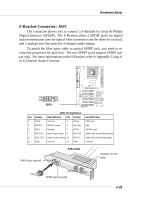
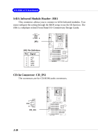
Hardware Setup S-Bracket Connector: JSP1 The connector allows you to connect a S-Bracket for Sony & Philips Digital Interface (SPDIF). The S-Bracket offers 2 SPDIF jacks for digital audio transmission (one for optical fiber connection and the other for coaxial), and 2 analog Line-Out jacks for 4-channel audio output. To attach the fiber-optic cable to optical SPDIF jack, you need to remove the plug from the jack first. The two SPDIF jacks support SPDIF output only. For more information on the S-Bracket, refer to Appendix. Using 4or 6-Channel Audio Function. 11 1 12 2 JSP1 JSP1 Pin Definition PIN SIGNAL DESCRIPTION PIN SIGNAL 1 VCC5 VCC 5V 2 VDD3 3 SPDFO S/PDIF output 4 (No Pin) 5 GND Ground 6 SPDFI 7 LFE-OUT Audio bass output 8 SOUT-R 9 CET-OUT Audio center output 10 SOUT-L 11 GND Ground 12 GND DESCRIPTION VDD 3.3V Key S/PDIF input Audio right surrounding output Audio left surrounding output Ground SPDIF jack (optical) S-Bracket Analog Line-Out jacks Plug CEN/SUB RL/RR SPDIF jack (coaxial) 2-21
-
 1
1 -
2
-
3
-
4
-
5
-
6
-
7
-
8
-
9
-
10
-
11
-
12
-
13
-
14
-
15
-
16
-
17
-
18
-
19
-
20
-
21
-
22
-
23
-
24
-
25
-
26
-
27
-
28
-
29
-
30
-
31
-
32
-
33
-
34
-
35
-
 36
36 -
 37
37 -
 38
38 -
 39
39 -
 40
40 -
 41
41 -
 42
42 -
 43
43 -
 44
44 -
 45
45 -
 46
46 -
47
-
48
-
49
-
50
-
51
-
52
-
53
-
54
-
55
-
56
-
57
-
58
-
59
-
60
-
61
-
62
-
63
-
64
-
65
-
66
-
67
-
68
-
69
-
70
-
71
-
72
-
73
-
74
-
75
-
76
-
77
-
78
-
79
-
80
-
81
-
82
-
83
-
84
-
85
-
86
-
87
-
88
-
89
-
90
-
91
-
92
-
93
-
94
-
95
-
96
-
97
-
98
-
99
-
100
-
101
-
102
-
103
-
104
-
105
-
106
-
107
 |
 |
