McAfee M-2750 Product Guide - Page 9
Front and back panel LEDs, Search the KnowledgeBase. - specifications
 |
View all McAfee M-2750 manuals
Add to My Manuals
Save this manual to your list of manuals |
Page 9 highlights
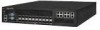
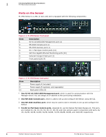
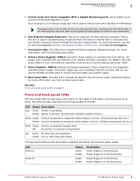
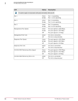
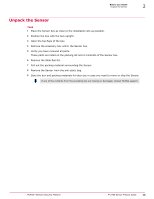
Introducing Network Security Sensors M-2750 physical description 1 5 Twenty small form-factor pluggable (SFP) 1 Gigabit Monitoring ports, which enable you to monitor ten Ethernet segments In-Line. If you choose to run in failover mode, port 10A is used to interconnect with a standby M-2750 Sensor. The gigabit ports of the M-2750 running in in-line mode fail-close, meaning that if the Sensor fails, it will interrupt/block data flow. Refer to the Gigabit Fail-Open Bypass Kit Guide for more information. 6 One External Compact Flash port. This port is used only for flash recovery purposes. That is, this port is used in troubleshooting situations where the Sensor's internal flash is corrupted and you need to reboot the Sensor through the external compact flash. For more information, see the on-line KnowledgeBase at http://mysupport.mcafee.com/Eservice/. Click Search the KnowledgeBase. 7 Front panel LEDs. The LEDs which indicate the Sensor's general operational status. For more information, see Front and back panel LEDs. 8 Primary Power Supplies-PWR A (included). Power supply A is included with each Sensor. The supply uses a standard IEC port (IEC320-C13). McAfee provides a standard; 2m NEMA 5-15P (US) power cable (3 wire). International customers must procure a country-appropriate power cable. 9 Power Supplies-PWR B (optional, purchased separately). Power supply B is a hot-swappable, redundant power supply. This power supply also uses a standard IEC320-C13 port, and you can use the McAfee-provided cable or acquire one that meets your specific needs. 10 Back panel LEDs. The LEDs which indicate the Sensor's fan and power supply operational status. For more information, see Front and back panel LEDs. See also Front and back panel LEDs on page 9 Front and back panel LEDs The front panel LEDs provide status information for the health of the Sensor and the activity on its ports. The following table describes the front panel LEDs of M-2750: LED Sys Status Description Green Sensor is operating. Amber Sensor is booting. (It could also indicate a system failure.) Temp Green Inlet air temperature measured inside chassis is normal. (Chassis temperature OK.) Amber Inlet air temperature measured inside chassis is too hot. (Chassis temperature too hot.) Flash Green Activity on external compact flash. Off No activity on external compact flash. Fan Green All three fans are operating. Amber One or more fans have failed. The back panel LEDs provide information regarding the Sensor fans and the power supply: LED Power A Power B Status Green Amber Green Amber Description Power Supply A is functioning. Power Supply A is not functioning. Power Supply B is functioning. Power Supply B is not functioning. McAfee® Network Security Platform M-2750 Sensor Product Guide 9
-
 1
1 -
2
-
3
-
 4
4 -
 5
5 -
 6
6 -
 7
7 -
 8
8 -
 9
9 -
 10
10 -
 11
11 -
 12
12 -
 13
13 -
 14
14 -
15
-
16
-
17
-
18
-
19
-
20
-
21
-
22
-
23
-
24
-
25
-
26
-
27
-
28
-
29
-
30
-
31
-
32
-
33
-
34
-
35
-
36
 |
 |