Netgear WFS709TP WFS709TP Hardware manual - Page 23
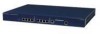
Requirements, The WFS709TP ProSafe Smart Wireless Switch is shipped with mounting brackets already
 |
UPC - 606449052336
View all Netgear WFS709TP manuals
Add to My Manuals
Save this manual to your list of manuals |
Page 23 highlights
WFS709TP ProSafe Smart Wireless Switch Hardware Installation Guide Requirements The WFS709TP ProSafe Smart Wireless Switch is shipped with mounting brackets already attached so that you can mount the chassis into a standard 19-inch equipment rack. Note: The four 12-24 screws included with the WFS709TP are intended for securing the chassis to the rack. Some racks require different sized screws which are not included. Make sure that you have the correct screws or fasteners for your rack system before attempting to mount the chassis. The WFS709TP, like other network and computing devices, requires compliance with operational specifications: • Reliable power - Make sure that your electrical outlet is compatible with the WFS709TP. For power requirements, see Appendix B, "Specifications". - Power cords must be rated to 10 A and must conform to grounded electrical standards in the country in which the WFS709TP operates. - Use of a power line conditioner or Uninterruptible Power Supply (UPS) can decrease or mitigate problems caused by power service fluctuations. Make sure that the output of any power shaping device is compatible with the WFS709TP power supply. • Cool, non-condensing ventilation - For operating environment information, see Appendix B, "Specifications". - Where a large number of electrical devices are running in the same area, additional air conditioning or air circulation equipment may be required. • Ample space - For proper air circulation, leave at least 10 cm (4 inches) clearance for the vents on the left and right of the chassis. - Leave additional space in front and back of the chassis to access power cords, network cables, and indicator LEDs. • Limited electromagnetic interference Installing the Chassis 2-3 v1.0, May 2007
-
 1
1 -
2
-
3
-
4
-
5
-
6
-
7
-
8
-
9
-
10
-
11
-
12
-
13
-
14
-
15
-
16
-
17
-
 18
18 -
 19
19 -
 20
20 -
 21
21 -
 22
22 -
 23
23 -
 24
24 -
 25
25 -
 26
26 -
 27
27 -
 28
28 -
29
-
30
-
31
-
32
-
33
-
34
-
35
-
36
 |
 |
