Netgear WFS709TP WFS709TP Hardware manual - Page 27
Verifying the Installation
 |
UPC - 606449052336
View all Netgear WFS709TP manuals
Add to My Manuals
Save this manual to your list of manuals |
Page 27 highlights
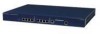
WFS709TP ProSafe Smart Wireless Switch Hardware Installation Guide 3. Make sure that the power supply can handle the connected Power over Ethernet (PoE) devices. Note: The total power drawn by all connected PoE devices must not exceed 100 Watts. For power ratings for NETGEAR APs, refer to the access point installation guide. 4. Attach the power cord to the power input socket at the back of the chassis. Plug an appropriate power cord into the power input socket. Use the included power cord if it is compatible with your electrical outlet. Otherwise, replace the power cord with the type appropriate for your country. The power input socket accepts a power cord with a standard IEC320 connector. Warning: For proper safety and performance, the power cord must be rated to 10 A and conform to grounded electrical standards in the country where the product is operated. 5. Attach the power cord to a proper electrical outlet to power up the WFS709TP. Warning: For safety reasons, make sure the power outlet and plug are within easy reach of the operator and can be quickly disconnected if necessary. Once power is connected, the WFS709TP automatically turns on and you can perform the power-on test. Verifying the Installation After the WFS709TP ProSafe Smart Wireless Switch is installed and connected to power, verify the following: 1. Check that the Power LED lights solid green immediately upon power up and remains solid green during and after boot. Note: The Status LED remains off until you perform the initial setup. Installing the Chassis 2-7 v1.0, May 2007
-
 1
1 -
2
-
3
-
4
-
5
-
6
-
7
-
8
-
9
-
10
-
11
-
12
-
13
-
14
-
15
-
16
-
17
-
18
-
19
-
20
-
21
-
 22
22 -
 23
23 -
 24
24 -
 25
25 -
 26
26 -
 27
27 -
 28
28 -
 29
29 -
 30
30 -
 31
31 -
 32
32 -
33
-
34
-
35
-
36
 |
 |
