Netgear WFS709TP WFS709TP Hardware manual - Page 25
Allow additional space in front and back of the chassis to access power cords, network, cables
 |
UPC - 606449052336
View all Netgear WFS709TP manuals
Add to My Manuals
Save this manual to your list of manuals |
Page 25 highlights
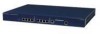
WFS709TP ProSafe Smart Wireless Switch Hardware Installation Guide Figure 2-1 • Use a Phillips or cross-head screwdriver to secure the chassis to the rack with two 12-24 screws (included) for each mounting bracket. Note: Some racks require different screws which are not included. Make sure that you use the correct screws or fasteners for your rack system. 3. Ensure that there is adequate clearance around the chassis (Figure 2-2 on page 2-6). • For proper air circulation, leave at least 10 cm (4 inches) clearance for the vents on the left and right of the chassis. • Allow additional space in front and back of the chassis to access power cords, network cables, and indicator LEDs. Installing the Chassis 2-5 v1.0, May 2007
-
 1
1 -
2
-
3
-
4
-
5
-
6
-
7
-
8
-
9
-
10
-
11
-
12
-
13
-
14
-
15
-
16
-
17
-
18
-
19
-
 20
20 -
 21
21 -
 22
22 -
 23
23 -
 24
24 -
 25
25 -
 26
26 -
 27
27 -
 28
28 -
 29
29 -
 30
30 -
31
-
32
-
33
-
34
-
35
-
36
 |
 |

WFS709TP ProSafe Smart Wireless Switch Hardware Installation Guide
Installing the Chassis
2-5
v1.0, May 2007
•
Use a Phillips or cross-head screwdriver to secure the chassis to the rack with two 12-24
screws (included) for each mounting bracket.
3.
Ensure that there is adequate clearance around the chassis (
Figure 2-2 on page 2-6
).
•
For proper air circulation, leave at least 10 cm (4 inches) clearance for the vents on the left
and right of the chassis.
•
Allow additional space in front and back of the chassis to access power cords, network
cables, and indicator LEDs.
Figure 2-1
Note:
Some racks require different screws which are not included. Make sure that
you use the correct screws or fasteners for your rack system.