Nokia NBB0150000 Installation Guide
Nokia NBB0150000 - IP150 - Security Appliance Manual
 |
View all Nokia NBB0150000 manuals
Add to My Manuals
Save this manual to your list of manuals |
Nokia NBB0150000 manual content summary:
- Nokia NBB0150000 | Installation Guide - Page 1
Nokia IP150 Security Platform Installation Guide Part No. N450000666 Rev 002 Published May 2008 - Nokia NBB0150000 | Installation Guide - Page 2
USERS This software and hardware is provided by Nokia goods or services; loss Nokia is a registered trademark of Nokia Corporation. Other products mentioned in this document are trademarks or registered trademarks of their respective holders. 080101 2 Nokia IP150 Security Platform Installation Guide - Nokia NBB0150000 | Installation Guide - Page 3
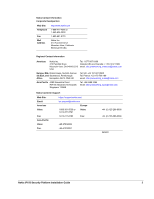
: Americas Voice: Fax: Asia-Pacific Voice: Fax: https://support.nokia.com/ [email protected] Europe 1-888-361-5030 or 1-613-271-6721 Voice: 1-613-271-8782 Fax: +65-67232999 +65-67232897 +44 (0) 125-286-8900 +44 (0) 125-286-5666 050602 Nokia IP150 Security Platform Installation Guide 3 - Nokia NBB0150000 | Installation Guide - Page 4
4 Nokia IP150 Security Platform Installation Guide - Nokia NBB0150000 | Installation Guide - Page 5
LEDs 18 Site Requirements 19 Product Disposal 19 Safety Warnings and Cautions 20 Managing IP150 Security Platform Appliances 20 2 Installing a Nokia IP150 Security Appliance 23 Rack Mounting a Nokia IP150 Appliance 23 3 Connecting to the Ethernet Ports 27 Built-In Four-Port 10/100/1000 - Nokia NBB0150000 | Installation Guide - Page 6
63 A Technical Specifications 67 Physical Dimensions 67 Space Requirements 67 Other Specifications 67 Appliance Interfaces 68 B Compliance Information 69 Declaration of Conformity 69 Compliance Statements 70 FCC Notice (US 71 Index 73 6 Nokia IP150 Security Platform Installation Guide - Nokia NBB0150000 | Installation Guide - Page 7
Tables Table 1 Text Conventions 12 Table 2 Pin Assignments for DB9 and DB25 Interface Cables 18 Table 3 Appliance Status LEDs 19 Nokia IP150 Security Platform Installation Guide 7 - Nokia NBB0150000 | Installation Guide - Page 8
8 Nokia IP150 Security Platform Installation Guide - Nokia NBB0150000 | Installation Guide - Page 9
Figure 5 Appliance Status LEDs 18 Figure 6 Installing the Mounting Brackets 24 Figure 7 Rack-mounted IP150 Appliance 25 Nokia Network Voyager Reference Access Points 37 Figure 12 Hard-Disk Drive Location 46 Figure 13 DIMM Socket Locations 50 Nokia IP150 Security Platform Installation Guide - Nokia NBB0150000 | Installation Guide - Page 10
10 Nokia IP150 Security Platform Installation Guide - Nokia NBB0150000 | Installation Guide - Page 11
of the Nokia IP150 Security Platform. „ Chapter 2, "Installing a Nokia IP150 Security Appliance" explains how to rack mount the appliance and how to physically connect it to a network and power. „ Chapter 3, "Connecting to the Ethernet Ports" describes how to connect to the supported Ethernet ports - Nokia NBB0150000 | Installation Guide - Page 12
or Enter key when an instruction says type. • Emphasizes a point or denotes new terms at the place where they are defined in the text. • Indicates an external book title reference. • Indicates a variable in a command: delete interface if_name 12 Nokia IP150 Security Platform Installation Guide - Nokia NBB0150000 | Installation Guide - Page 13
support.nokia.com). You can access inline help, the Nokia Network Voyager Reference Guide, and the CLI Reference Guide from Nokia Network Voyager. Check Point documentation is available from the Check Point Web site at: http:// www.checkpoint.com/ 060306 Nokia IP150 Security Platform Installation - Nokia NBB0150000 | Installation Guide - Page 14
1 About this Guide 14 Nokia IP150 Security Platform Installation Guide - Nokia NBB0150000 | Installation Guide - Page 15
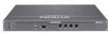
access, and achieve regulatory compliance. For technical specifications, see "Technical Specifications" on page 67. Nokia IP150 Security Platform Appliance Overview The following figures show component locations for Nokia IP150 appliances. Nokia IP150 Security Platform Installation Guide 15 - Nokia NBB0150000 | Installation Guide - Page 16
built-in Ethernet ports and LEDs. Figure 3 Built-In Ethernet Interface Front Panel Details Activity LED (yellow) Link LED (green) 00120 RJ-45 connectors 16 Nokia IP150 Security Platform Installation Guide - Nokia NBB0150000 | Installation Guide - Page 17
Console Connections 1 Input or 5 Pin# Assignment output 1 6 9 2 00460 3 not used RXD TXD Input Output 4 DTR Output 5 GND 6 DSR Input 7 RTS Output 8 CTS Input 9 not used Nokia IP150 Security Platform Installation Guide 17 - Nokia NBB0150000 | Installation Guide - Page 18
appliances by checking their status LEDs. The system status LEDs are located on the front panel of the appliance, as Figure 5 shows. Figure 5 Appliance Status LEDs POWER STATUS FAULT AUX CONSOLE Power Status Fault 1 2 3 4 IP150 00662 18 Nokia IP150 Security Platform Installation Guide - Nokia NBB0150000 | Installation Guide - Page 19
. Site Requirements Before you install a Nokia IP150 appliance, ensure that your computer room or wiring closet conforms to the environmental specifications listed in Appendix A, "Technical Specifications." Product Disposal At the end of its useful life, your appliance and all peripherals included - Nokia NBB0150000 | Installation Guide - Page 20
Voyager and the related reference materials, see "Using Nokia Network Voyager" on page 35. „ The Nokia IPSO command-line interface (CLI)-an SSHv2-secured interface that enables you to configure Nokia IP security platforms from the command line. 20 Nokia IP150 Security Platform Installation Guide - Nokia NBB0150000 | Installation Guide - Page 21
FireWall-1. Horizon Manager can perform installations and upgrades on up to 2,500 Nokia IP security platforms, offering administrators the most rapid and dependable upgrade to Check Point NG. For information about how to obtain Horizon Manager, see "Nokia Contact Information" on page 3. Nokia IP150 - Nokia NBB0150000 | Installation Guide - Page 22
1 22 Nokia IP150 Security Platform Installation Guide - Nokia NBB0150000 | Installation Guide - Page 23
a Nokia IP150 Appliance Before you mount the appliance on the rack, install the two side brackets with three screws on each side as shown in Figure 6. The brackets and screws are included with the materials you receive with the appliance. Nokia IP150 Security Platform Installation Guide 23 - Nokia NBB0150000 | Installation Guide - Page 24
2 Figure 6 Installing the Mounting Brackets POWER STATUS FAULT AUX CONSOLE 1 2 3 4 IP150 Serrated notches face up 00666 You can mount IP150 appliances in a standard 19-inch rack with three mounting screws as Figure 6 shows. 24 Nokia IP150 Security Platform Installation Guide - Nokia NBB0150000 | Installation Guide - Page 25
Figure 7 Rack-mounted IP150 Appliance POWER STATUS FAULT AUX CONSOLE 1 2 3 4 IP150 00682 Nokia IP150 Security Platform Installation Guide 25 - Nokia NBB0150000 | Installation Guide - Page 26
2 26 Nokia IP150 Security Platform Installation Guide - Nokia NBB0150000 | Installation Guide - Page 27
version of Nokia IPSO you are using. After the power is turned on, the Ethernet link LEDs on the appliance and on the remote equipment illuminate to indicate the connection. As data is transmitted, the activity LEDs on the appliance illuminates. Nokia IP150 Security Platform Installation Guide 27 - Nokia NBB0150000 | Installation Guide - Page 28
, with the copper tabs facing down and toward you. Figure 8 Output Connector for the Ethernet Cable 1 8 00270.1a Pin# Assignment 1 TX 2 TX 3 RX 4 5 6 RX 7 8 28 Nokia IP150 Security Platform Installation Guide - Nokia NBB0150000 | Installation Guide - Page 29
Built-In Four-Port 10/100/1000 Ethernet Interface The following figure shows the pin assignments for the RJ-45 crossover cable. Figure 9 Ethernet Crossover Cable Pin Connections 1 1 2 2 3 3 4 4 5 5 6 6 7 7 8 8 00017.1 Nokia IP150 Security Platform Installation Guide 29 - Nokia NBB0150000 | Installation Guide - Page 30
3 30 Nokia IP150 Security Platform Installation Guide - Nokia NBB0150000 | Installation Guide - Page 31
provide the initial configuration information the first time the appliance is started. „ Perform the initial configuration manually by using a console connection. This chapter describes how configured with the following settings for the console: Nokia IP150 Security Platform Installation Guide 31 - Nokia NBB0150000 | Installation Guide - Page 32
Power and Turning the Power On A power switch and a receptacle for the power cord are located on each power supply on the back of the appliance as shown in Figure 10. Figure 10 Power Switch Location Power plug 00663 Power switch 32 Nokia IP150 Security Platform Installation Guide - Nokia NBB0150000 | Installation Guide - Page 33
appliance. If the fans are still not running, or if the power LED does not illuminate, contact your Nokia service provider as listed in "Nokia Contact Information" on page 3 for technical support , the system activates the Nokia IPSO boot manager. Nokia IP150 Security Platform Installation Guide 33 - Nokia NBB0150000 | Installation Guide - Page 34
might configure the appliance with an incorrect host name and IP address (this could happen if a DHCP server on your network is configured to respond to any request). To reset the incorrect host and use Network Voyager to configure them. 34 Nokia IP150 Security Platform Installation Guide - Nokia NBB0150000 | Installation Guide - Page 35
a network routing problem. Confirm the information you entered during the initial configuration and check that all cables are firmly connected. For more information, see the troubleshooting section in the installation guide for your appliance. Nokia IP150 Security Platform Installation Guide 35 - Nokia NBB0150000 | Installation Guide - Page 36
Nokia Network Voyager. Inline help is the context-sensitive information source for Network Voyager. To access inline help for the window you are viewing, click Help. A Close button is available at the bottom of each inline help window you view. 36 Nokia IP150 Security Platform Installation Guide - Nokia NBB0150000 | Installation Guide - Page 37
section in the CLI Reference Guide for the version of Nokia IPSO you are using. 2. If you log in as a monitor user, you can execute only the the Nokia IPSO shell. The Nokia IPSO shell is what you see when you initially log on to the appliance. Nokia IP150 Security Platform Installation Guide 37 - Nokia NBB0150000 | Installation Guide - Page 38
enterprise, managed service provider (MSP), or hosted applications service provider network (ASP). For information about how to obtain Horizon Manager or to learn more about the Horizon Manager, see "Nokia Contact Information" on page 3. 060228 38 Nokia IP150 Security Platform Installation Guide - Nokia NBB0150000 | Installation Guide - Page 39
Using Check Point SmartCenter and Provider-1 Using Check Point SmartCenter and Provider-1 Nokia supports managing IP150 appliances with Check Point SmartCenter and Provider-1 Nokia IP150 Security Platform Installation Guide 39 - Nokia NBB0150000 | Installation Guide - Page 40
4 40 Nokia IP150 Security Platform Installation Guide - Nokia NBB0150000 | Installation Guide - Page 41
provides information on how to install or replace user serviceable items in your IP150 appliance. The following topics are covered: „ Replacing the Compact Flash Memory Card „ Replacing a Hard-Disk Drive „ Replacing or Upgrading Memory „ Installing or Replacing the Nokia Encryption Accelerator Card - Nokia NBB0150000 | Installation Guide - Page 42
. To use the CLI to shut the appliance down, enter halt at the prompt. 2. Remove the power cord from the IP150 appliance, and remove the appliance from the rack. 3. Turn the appliance upside down and place it on a safe and protected work surface 42 Nokia IP150 Security Platform Installation Guide - Nokia NBB0150000 | Installation Guide - Page 43
Replacing the Compact Flash Memory Card 4. Remove the three bottom-cover screws, and remove the cover as shown in the following figure. 00676 IP150 1 2 3 4 AUX CONSOLE POWER STATUS FAULT Nokia IP150 Security Platform Installation Guide 43 - Nokia NBB0150000 | Installation Guide - Page 44
5 5. Gently remove the installed compact flash memory card. Avoid pressing down on the surface of the card as much as possible. 00678 44 Nokia IP150 Security Platform Installation Guide - Nokia NBB0150000 | Installation Guide - Page 45
power cord. 8. Turn on the power supply at the back of the appliance. Replacing a Hard-Disk Drive You can replace the hard-disk drive to your IP150 appliance. The following figure shows the location of the hard-disk drive on the motherboard. Nokia IP150 Security Platform Installation Guide 45 - Nokia NBB0150000 | Installation Guide - Page 46
strap and follow the instructions provided with the wrist strap before you handle the components or open the appliance. If you do not appliance and turn the power off whenever you remove the chassis tray assembly to service internal components. 46 Nokia IP150 Security Platform Installation Guide - Nokia NBB0150000 | Installation Guide - Page 47
it on a safe and protected work surface. 4. Remove the three top-cover screws and slide the cover back to remove it from the appliance. 00667 5. Locate the hard-disk drive installation location and disconnect the two connectors from the drive. Nokia IP150 Security Platform Installation Guide 47 - Nokia NBB0150000 | Installation Guide - Page 48
drive assembly from the appliance, remove the four drive bracket screws, and remove the assembly. 00674 7. Remove the retaining screws that hold the drive unit from the sides of the bracket, and remove the drive from the bracket. 00675 48 Nokia IP150 Security Platform Installation Guide - Nokia NBB0150000 | Installation Guide - Page 49
manner as you removed it. 00674a 00675a 9. Reinstall the two drive connectors. 10. Replace the top cover, reinstall the appliance in the rack, and reconnect the appliance power cord. 11. Turn on the power supply at the back of the appliance. Nokia IP150 Security Platform Installation Guide 49 - Nokia NBB0150000 | Installation Guide - Page 50
DIMM sockets are located at the right of the motherboard, as you look at the appliance from the front, as Figure 13 shows. Figure 13 DIMM Socket Locations DIMMs and DIMM sockets Note: Shown here with bottom cover already removed. 00677 1 2 3 4 50 Nokia IP150 Security Platform Installation Guide - Nokia NBB0150000 | Installation Guide - Page 51
. To use the CLI to shut the appliance down, enter halt at the prompt. 2. Remove the power cord from the IP150 appliance, and remove the appliance from the rack. 3. Turn the appliance upside down and place it on a safe and protected work surface Nokia IP150 Security Platform Installation Guide 51 - Nokia NBB0150000 | Installation Guide - Page 52
5 4. Remove the three bottom-cover screws, and remove the cover as shown in the following figure. IP150 1 2 3 4 AUX CONSOLE POWER STATUS FAULT 00676 52 Nokia IP150 Security Platform Installation Guide - Nokia NBB0150000 | Installation Guide - Page 53
opposite ends of the DIMM alternately to gradually free it from the contact pins. 6. The memory DIMMs are keyed to prevent improper insertion. Press the new DIMM into the socket until it clicks into place and the retaining clips lock into position. Nokia IP150 Security Platform Installation Guide - Nokia NBB0150000 | Installation Guide - Page 54
speed cryptographic processing that enhances VPN performance. You can install or replace the Nokia encryption accelerator card in your IP150 appliance. The following figure shows the location of the encryption accelerator card on the motherboard. 54 Nokia IP150 Security Platform Installation Guide - Nokia NBB0150000 | Installation Guide - Page 55
use the CLI to shut the appliance down, enter halt at the prompt. 2. Remove the power cord from the IP150 appliance, and remove the appliance from the rack. 3. Place the appliance right-side up and place it on a safe and protected work surface. Nokia IP150 Security Platform Installation Guide 55 - Nokia NBB0150000 | Installation Guide - Page 56
top-cover screws and slide the cover back to remove it from the appliance. 00667 5. If you need to remove an installed encryption accelerator card, pull the two retaining clips outward as shown in the following figure. 1 2 3 4 IP150 00670 56 Nokia IP150 Security Platform Installation Guide - Nokia NBB0150000 | Installation Guide - Page 57
You can also configure the IP150 appliances to use the Nokia encryption accelerator card for IKE acceleration. When you enable IKE acceleration, the Nokia encryption accelerator card performs cryptographic operations for IPsec tunnel negotiation. Nokia IP150 Security Platform Installation Guide 57 - Nokia NBB0150000 | Installation Guide - Page 58
to the manufacturer's instructions. Warning Make certain to remove the power cord from the appliance before you proceed with any of the following steps. Failure to do so could cause electric shock with burns or death resulting for the user. 58 Nokia IP150 Security Platform Installation Guide - Nokia NBB0150000 | Installation Guide - Page 59
the IP150 appliance, and remove the appliance from the rack. 3. Turn the appliance right-side up and place it on a safe and protected work surface. 4. Remove the three top-cover screws and slide the cover back to remove it from the appliance. 00667 Nokia IP150 Security Platform Installation Guide - Nokia NBB0150000 | Installation Guide - Page 60
You must place the new battery into the battery holder observing the correct polarity. The positive terminal of the battery must be facing up. 60 Nokia IP150 Security Platform Installation Guide - Nokia NBB0150000 | Installation Guide - Page 61
top cover, reinstall the appliance in the rack, and reconnect the appliance power cord. 9. Turn on the power supply at the back of the appliance. After you replace the battery, you need to reset the date and time using Network Voyager or the CLI. Nokia IP150 Security Platform Installation Guide 61 - Nokia NBB0150000 | Installation Guide - Page 62
5 62 Nokia IP150 Security Platform Installation Guide - Nokia NBB0150000 | Installation Guide - Page 63
This chapter provides troubleshooting tips, problems, and solutions related to Nokia IP150 appliance installations. For information about how to reinstall Nokia IPSO on to your appliance, see the Nokia IPSO Boot Manager Reference Guide for the version of Nokia IPSO that you are using - Nokia NBB0150000 | Installation Guide - Page 64
. Do Not Receive a Login Prompt-Error Messages Appear Problem The IP150 appliance is defective, or the file system on the appliance is defective. Solution Contact the Nokia customer support site listed in "Nokia Contact Information" on page 3. 64 Nokia IP150 Security Platform Installation Guide - Nokia NBB0150000 | Installation Guide - Page 65
have set the wrong speed. Verify that the speeds match on each end of the Ethernet connection (10 or 100 Mbps). Problem Port not enabled. Solution Verify from the Interface page in Network Voyager that the interface port is configured as active. Nokia IP150 Security Platform Installation Guide 65 - Nokia NBB0150000 | Installation Guide - Page 66
6 Problem High collision rate on the hub. Solution Disconnect connections one at a time until the problem is localized to one computer and troubleshoot further. 66 Nokia IP150 Security Platform Installation Guide - Nokia NBB0150000 | Installation Guide - Page 67
40° Celsius) Humidity 10% to 90% (non-condensing) Non-operating temperature range 23° to 113° (-5° to 45° Celsius) Non-operating humidity 5% to 95% (non-condensing) Nokia IP150 Security Platform Installation Guide 67 - Nokia NBB0150000 | Installation Guide - Page 68
320 hours At 40°: 54,088 hours 100-120V/200-240V 50/60Hz 4.0A 55 watts Appliance Interfaces Interface Cable Type Ethernet IEEE 802.3 10/100 BASE-TX, 1000 BASE-T unshielded twisted pair, full-duplex or half-duplex Cable Output Connector RJ-45 68 Nokia IP150 Security Platform Installation Guide - Nokia NBB0150000 | Installation Guide - Page 69
that the product: Product Name: Model Number: Product Options: Serial Number: Date First Applied: IP150 IP150, IP151 All 1 to 100,000 2008 conforms to the following standards: Safety: UL 60950-1, 23/EEC and the EMC Directive 2004/108/EC. Nokia IP150 Security Platform Installation Guide 69 - Nokia NBB0150000 | Installation Guide - Page 70
B Christopher Saleem Compliance & Reliability Engineering Manager Security & Mobile Connectivity, Enterprise Solutions Mountain View, California and Voltage Fluctuation EN61000-3-2 European Community (CE) EN61000-3-3 European Community (CE) 70 Nokia IP150 Security Platform Installation Guide - Nokia NBB0150000 | Installation Guide - Page 71
in which case the user will be required to correct the interference at his own expense. Caution Any changes or modifications not expressly approved by the grantee of this device could void the user's authority to operate the equipment. 050316 Nokia IP150 Security Platform Installation Guide 71 - Nokia NBB0150000 | Installation Guide - Page 72
B 72 Nokia IP150 Security Platform Installation Guide - Nokia NBB0150000 | Installation Guide - Page 73
-disk drive installing a 45 I installing hard-disk drive, a 45 interfaces connecting network 35 IP150 appliances monitoring 18 M memory (RAM) replacing 50 upgrading 50 modem connection pin assignments for the 17 monitoring IP150 appliances 18 Nokia IP150 Security Platform Installation Guide Index - Nokia NBB0150000 | Installation Guide - Page 74
equipment 19 replacing RAM memory 50 RJ-45 connector 28, 29 S security platform configuring 31 specifications interfaces 68 space requirements 67 T technical specifications See specifications troubleshooting 63 U upgrading RAM memory 50 Index - 74 Nokia IP150 Security Platform Installation Guide
-
 1
1 -
 2
2 -
 3
3 -
 4
4 -
 5
5 -
 6
6 -
 7
7 -
8
-
9
-
10
-
11
-
12
-
13
-
14
-
15
-
16
-
17
-
18
-
19
-
20
-
21
-
22
-
23
-
24
-
25
-
26
-
27
-
28
-
29
-
30
-
31
-
32
-
33
-
34
-
35
-
36
-
37
-
38
-
39
-
40
-
41
-
42
-
43
-
44
-
45
-
46
-
47
-
48
-
49
-
50
-
51
-
52
-
53
-
54
-
55
-
56
-
57
-
58
-
59
-
60
-
61
-
62
-
63
-
64
-
65
-
66
-
67
-
68
-
69
-
70
-
71
-
72
-
73
-
74
 |
 |

Part No. N450000666 Rev 002
Published May 2008
Nokia IP150 Security Platform
Installation Guide