Nokia NBB0150000 Installation Guide - Page 18
System Status LEDs, Nokia IP150 Security Platform Installation Guide, Appliance Status LEDs
 |
View all Nokia NBB0150000 manuals
Add to My Manuals
Save this manual to your list of manuals |
Page 18 highlights
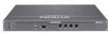
1 Table 2 shows how to match pins at the console connector with output pins on DB9 or DB25 cables you are using with terminal devices or other appropriate equipment. Table 2 Pin Assignments for DB9 and DB25 Interface Cables Console or serial DB9 cable output pin and DB25 cable output pin and pin and assignment assignment assignment Shield (FG) Shield (FG) 1 (FG) 2 (RXD) 3 (TXD) 2 (TXD) 3 (TXD) 2 (RXD) 3 (RXD) 4 (DTR) 6 (DSR) 6 (DSR) 5 (SG) 5 (SG) 7 (SG) 6 (DSR) 4 (DTR) 20 (DTR) 7 (RTS) 8 (CTS) 5 (CTS) 8 (CTS) 7 (RTS) 4 (RTS) System Status LEDs You can monitor the basic operation of Nokia IP150 appliances by checking their status LEDs. The system status LEDs are located on the front panel of the appliance, as Figure 5 shows. Figure 5 Appliance Status LEDs POWER STATUS FAULT AUX CONSOLE Power Status Fault 1 2 3 4 IP150 00662 18 Nokia IP150 Security Platform Installation Guide
-
 1
1 -
2
-
3
-
4
-
5
-
6
-
7
-
8
-
9
-
10
-
11
-
12
-
 13
13 -
 14
14 -
 15
15 -
 16
16 -
 17
17 -
 18
18 -
 19
19 -
 20
20 -
 21
21 -
 22
22 -
 23
23 -
24
-
25
-
26
-
27
-
28
-
29
-
30
-
31
-
32
-
33
-
34
-
35
-
36
-
37
-
38
-
39
-
40
-
41
-
42
-
43
-
44
-
45
-
46
-
47
-
48
-
49
-
50
-
51
-
52
-
53
-
54
-
55
-
56
-
57
-
58
-
59
-
60
-
61
-
62
-
63
-
64
-
65
-
66
-
67
-
68
-
69
-
70
-
71
-
72
-
73
-
74
 |
 |
