Optoma HD7100 User Manual - Page 59
Connecting Pin Assignments
 |
UPC - 796435218140
View all Optoma HD7100 manuals
Add to My Manuals
Save this manual to your list of manuals |
Page 59 highlights
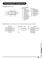
Connecting Pin Assignments DVI-D port: 25 pin connector 24 23 ~ 18 17 C1 8 7 ~ 21 16 ~ 9 • DVI Digital INPUT Pin No.Signal Pin No.Signal 1 T.M.D.S data 22 T.M.D.S data 2+ 16 Hot plug detection 17 T.M.D.S data 0- 3 T.M.D.S data 2 shield 18 T.M.D.S data 0+ 4 Not connected 19 T.M.D.S data 0 shield 5 Not connected 20 Not connected 6 DDC clock 21 Not connected 7 DDC data 22 T.M.D.S clock shield 8 Not connected 23 T.M.D.S clock+ 9 T.M.D.S data 1- 24 T.M.D.S clock- 10 T.M.D.S data 1+ C1 Ground 11 T.M.D.S data 1 shield 12 Not connected 13 Not connected 14 +5V power from graphic card. 15 Ground RS-232C Port: 9-pin D-sub Female connector of the DIN-D-sub RS-232Cvt cable pin connector 54321 9876 Pin No. Signal Name 1 2 SD Send Data 3 RD Receive Data 4 5 SG Signal Ground 6 7 8 9 I/O Input Output Reference Not connected Connected to internal circuit Connected to internal circuit Not connected Connected to internal circuit Not connected Not connected Not connected Not connected Appendix 59
-
 1
1 -
2
-
3
-
4
-
5
-
6
-
7
-
8
-
9
-
10
-
11
-
12
-
13
-
14
-
15
-
16
-
17
-
18
-
19
-
20
-
21
-
22
-
23
-
24
-
25
-
26
-
27
-
28
-
29
-
30
-
31
-
32
-
33
-
34
-
35
-
36
-
37
-
38
-
39
-
40
-
41
-
42
-
43
-
44
-
45
-
46
-
47
-
48
-
49
-
50
-
51
-
52
-
53
-
 54
54 -
 55
55 -
 56
56 -
 57
57 -
 58
58 -
 59
59 -
 60
60 -
 61
61 -
 62
62 -
 63
63 -
 64
64
 |
 |
