Pioneer AVIC-X920BT Installation Manual - Page 17
When connecting the, external video component, Connecting the System
 |
UPC - 884938104241
View all Pioneer AVIC-X920BT manuals
Add to My Manuals
Save this manual to your list of manuals |
Page 17 highlights
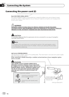
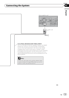
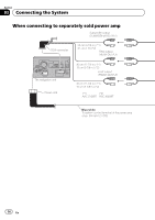
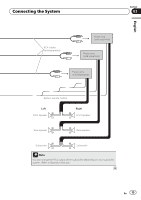
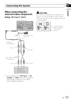
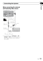
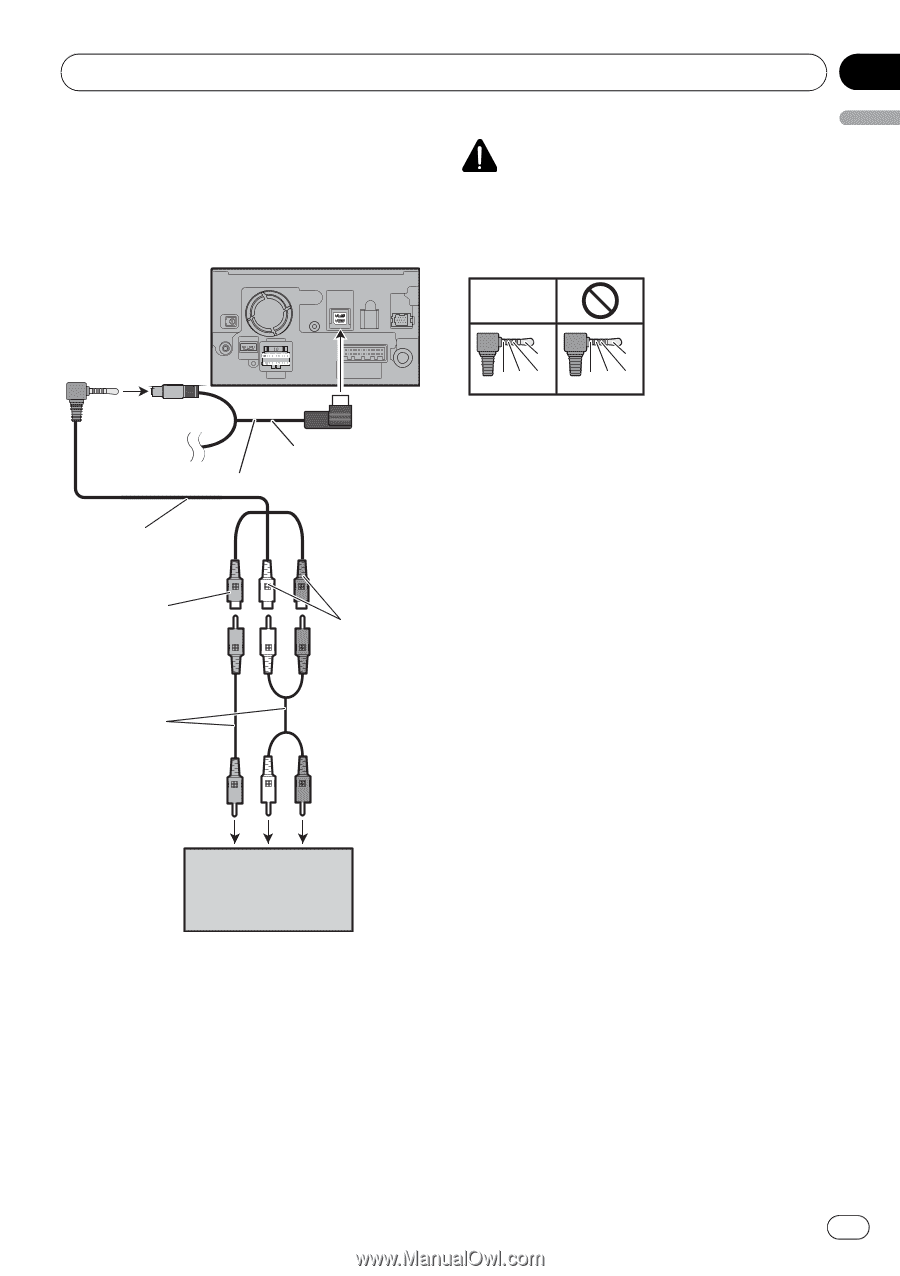
Connecting the System Section 03 English When connecting the external video component Using "AV1 Input" (AV1) The navigation unit CAUTION Be sure to use a CD-RM10 (sold separately) for wiring. If you use other cables, there is a case where wiring position differs, images and sounds may be disturbed. OK L VGR L RG V L : Left audio (White) R : Right audio (Red) V : Video (Yellow) G : Ground USB and mini-jack connector 2 m (6 ft. 7 in.) CD-RM10 (sold separately) Yellow Red, white RCA cables (sold separately) To video output To audio outputs External video component (sold separately) ! It is necessary to set "AV1 Input" in "AV Settings" to "Video" when connecting the external video component. (For details, refer to Operation Manual.) En 17
-
 1
1 -
2
-
3
-
4
-
5
-
6
-
7
-
8
-
9
-
10
-
11
-
 12
12 -
 13
13 -
 14
14 -
 15
15 -
 16
16 -
 17
17 -
 18
18 -
 19
19 -
 20
20 -
 21
21 -
 22
22 -
23
-
24
-
25
-
26
-
27
-
28
-
29
-
30
-
31
-
32
-
33
-
34
-
35
-
36
-
37
-
38
-
39
-
40
-
41
-
42
-
43
-
44
-
45
-
46
-
47
-
48
-
49
-
50
-
51
-
52
-
53
-
54
-
55
-
56
 |
 |
When connecting the
external video component
Using
“
AV1 Input
”
(
AV1
)
The navigation unit
RCA cables
(
sold separately)
Yellow
Red, white
External
component
(sold separately)
video
To video output
To audio outputs
CD-RM10
(sold separately)
USB and mini-jack
connector
2 m (6 ft. 7 in.)
!
It is necessary to set
“
AV1 Input
”
in
“
AV
Settings
”
to
“
Video
”
when connecting the
external video component. (For details,
refer to Operation Manual.)
CAUTION
Be sure to use a CD-RM10 (sold separately) for
wiring. If you use other cables, there is a case
where wiring position differs, images and sounds
may be disturbed.
OK
G
V
R
L
G
R
V
L
L :
Left audio (White)
R :
Right audio (Red)
V :
Video (Yellow)
G :
Ground
En
17
English
Section
03
Connecting the System