Pioneer AVIC-X920BT Installation Manual - Page 22
Installation - parts
 |
UPC - 884938104241
View all Pioneer AVIC-X920BT manuals
Add to My Manuals
Save this manual to your list of manuals |
Page 22 highlights
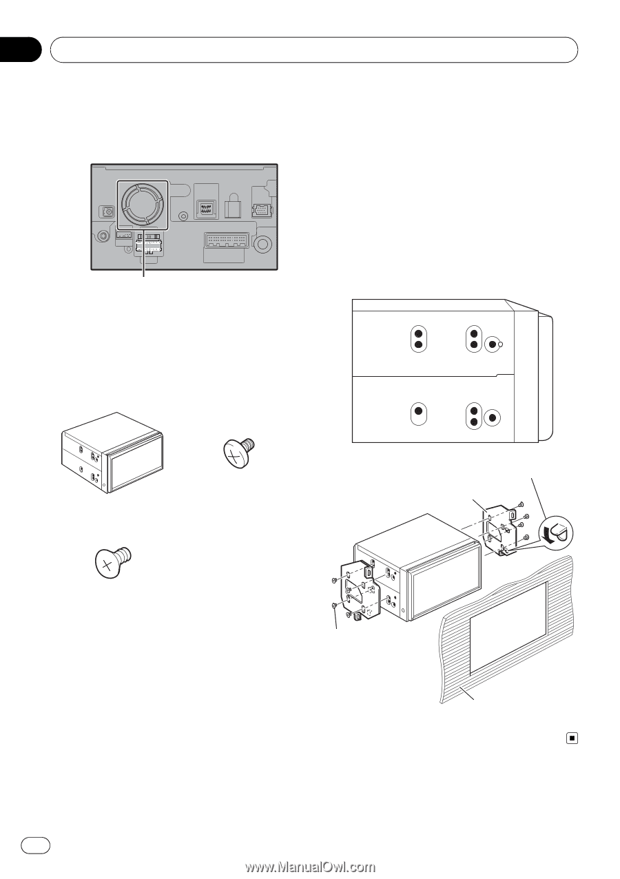
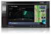
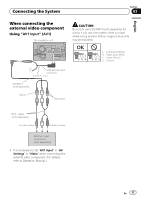
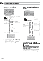
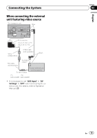
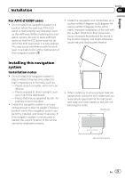
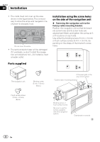
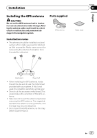
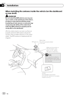
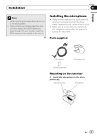
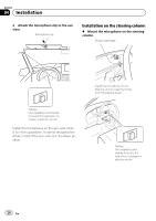
Section 04 Installation ! The cords must not cover up the area shown in the figure below. This is necessary to allow the amps and navigation mechanism to dissipate heat. Do not cover this area. ! The semiconductor laser will be damaged if it overheats, so don't install the navigation unit anywhere hot -for instance, near a heater outlet. Installation using the screw holes on the side of the navigation unit % Fastening the navigation unit to the factory radio-mounting bracket. Position the navigation unit so that the brackets screw holes and its screw holes are aligned (are fitted), and tighten the screws at 3 or 4 locations on each side. Use either the binding screws (5 mm × 8 mm) or flush surface screws (5 mm × 8 mm), depending on the shape of the bracket's screw holes. Parts supplied The navigation unit Binding screw (5 mm × 8 mm) (8 pcs.) Flush surface screw (5 mm × 8 mm) (8 pcs.) If the pawl gets in the way, bend it down Factory radio mounting bracket Binding screw or flush surface screw Be sure to use the screws supplied with this navigation system. Dashboard or console 22 En
-
 1
1 -
2
-
3
-
4
-
5
-
6
-
7
-
8
-
9
-
10
-
11
-
12
-
13
-
14
-
15
-
16
-
 17
17 -
 18
18 -
 19
19 -
 20
20 -
 21
21 -
 22
22 -
 23
23 -
 24
24 -
 25
25 -
 26
26 -
 27
27 -
28
-
29
-
30
-
31
-
32
-
33
-
34
-
35
-
36
-
37
-
38
-
39
-
40
-
41
-
42
-
43
-
44
-
45
-
46
-
47
-
48
-
49
-
50
-
51
-
52
-
53
-
54
-
55
-
56
 |
 |