ProForm 420 Zle Elliptical Uk Manual - Page 5
Part Identification Chart
 |
View all ProForm 420 Zle Elliptical manuals
Add to My Manuals
Save this manual to your list of manuals |
Page 5 highlights
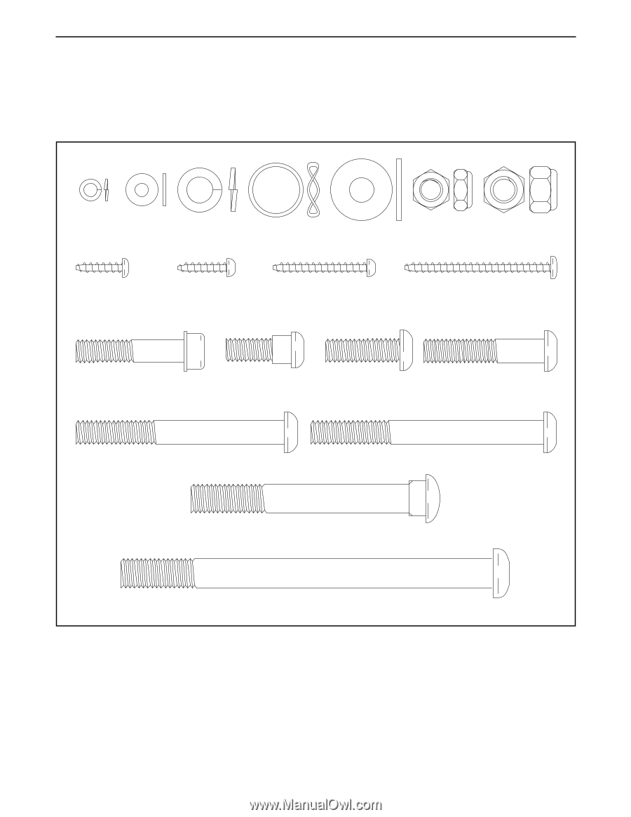
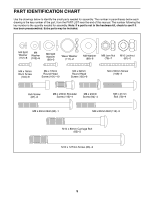
PART IDENTIFICATION CHART Use the drawings below to identify the small parts needed for assembly. The number in parentheses below each drawing is the key number of the part, from the PART LIST near the end of this manual. The number following the key number is the quantity needed for assembly. Note: If a part is not in the hardware kit, check to see if it has been preassembled. Extra parts may be included. M4 Split Washer (112)–-8 M4 Washer (102)–-8 M8 Split Washer (90)–-3 Wave Washer (111)–-2 M8 Washer (88)–-6 M8 Jam Nut (79)–-7 M10 Locknut (81)–-2 M4 x 16mm Blunt Screw (104)–-8 M4 x 16mm Round Head Screw (101)–-10 M4 x 32mm Round Head Screw (105)–-6 M4 x 50mm Screw (108)–-2 Hub Screw (87)–-8 M8 x 23mm Shoulder Screw (115)–-4 M8 x 23mm Screw (84)–-4 M8 x 41mm Bolt (78)–-4 M8 x 69mm Bolt (80)–-1 M8 x 80mm Bolt (116)–-2 M10 x 80mm Carriage Bolt (82)–-2 M10 x 127mm Screw (83)–-2 5
-
 1
1 -
 2
2 -
 3
3 -
 4
4 -
 5
5 -
 6
6 -
 7
7 -
 8
8 -
 9
9 -
 10
10 -
 11
11 -
12
-
13
-
14
-
15
-
16
-
17
-
18
-
19
-
20
-
21
-
22
-
23
-
24
-
25
-
26
-
27
-
28
 |
 |