ProForm 475 Audio Series Treadmill Uk Manual - Page 9
Console May Be Damaged When
 |
View all ProForm 475 Audio Series Treadmill manuals
Add to My Manuals
Save this manual to your list of manuals |
Page 9 highlights
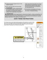
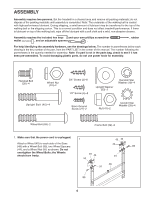
7. Set the Console (25) face down on a soft surface to avoid scratching the Console. Identify the Right Handrail (11), which has a large hole in the location shown. Set the Right Handrail on the Console as shown. Attach the Right Handrail with three 3/4" Screws (2). Make sure that no wires are pinched. Start all three Screws before tightening any of them. Do not overtighten the Screws. Next, attach the console ground wire to the Right Handrail (11) with a Silver Ground Screw (27). 7 11 Large Hole Console Ground Wire 27 Console Wire 2 2 2 25 Then, attach the Left Handrail (not shown) to the other side of the Console (25) as described above. Note: There are no wires on the other side of the Console. 8. Pull the indicated wire until the Upright Wire (28) is extending from the upper end of the Right 8 Upright (36). Slide the Right and Left Base Leg Covers (101, 102) onto the Left and Right Uprights (31, 36) and press them onto the Base (48) as shown. If necessary, pry lightly on the sides of the Base Leg Covers to fit them over the Wheel Nuts and Bolts (not shown). Wire 31 101 28 36 102 9. Insert the wire on the Upright Wire (28) up through the large holes in the Right Handrail (11) as shown. Pull the Upright Wire up through the holes. Next, set the Right Handrail and the Left Handrail (not shown), with the Console (25), onto the top of the Right Upright (36) and the Left Upright (not shown). Make sure that no wires are pinched. Then, untie and discard the wire. Connect the Upright Wire (28) to the console wire. Make sure to connect the connectors properly (see the inset drawing). The connectors should slide together easily and snap into place. If the connectors do not slide together easily and snap into place, turn one connector and try again. IF THE CONNECTORS ARE NOT CONNECTED PROPERLY, THE CONSOLE MAY BE DAMAGED WHEN THE POWER IS TURNED ON. Insert the connectors and excess wire into the Console (25). 9 25 11 28 9 48 Wire Console Wire 36 28
-
 1
1 -
2
-
3
-
 4
4 -
 5
5 -
 6
6 -
 7
7 -
 8
8 -
 9
9 -
 10
10 -
 11
11 -
 12
12 -
 13
13 -
 14
14 -
15
-
16
-
17
-
18
-
19
-
20
-
21
-
22
-
23
-
24
-
25
-
26
-
27
-
28
-
29
-
30
-
31
 |
 |
