ProForm 510 Es Elliptical English Manual - Page 25
How To Adjust The Drive Belt
 |
View all ProForm 510 Es Elliptical manuals
Add to My Manuals
Save this manual to your list of manuals |
Page 25 highlights
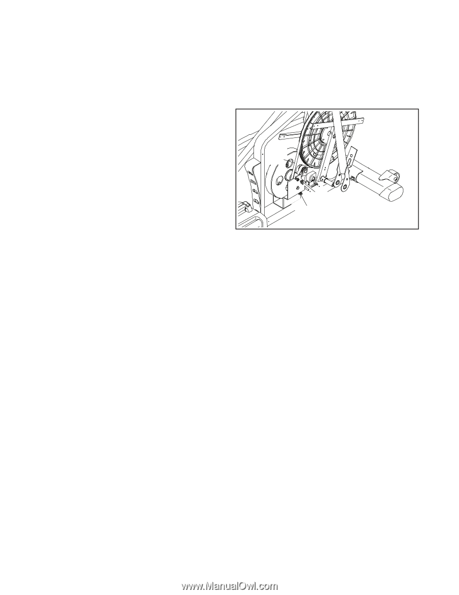
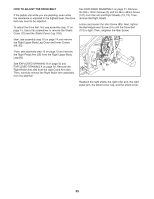
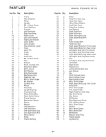
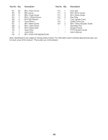
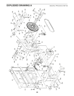
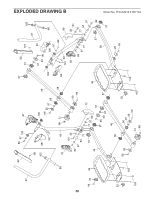
HOW TO ADJUST THE DRIVE BELT If the pedals slip while you are pedaling, even while the resistance is adjusted to the highest level, the drive belt may need to be adjusted. To adjust the drive belt, first see assembly step 17 on page 15. Use a flat screwdriver to remove the Shield Cover (75) and the Shield Cover Cap (118). See EXPLODED DRAWING C on page 31. Remove the M4 x 19mm Screws (5) and the M4 x 48mm Screw (107) from the Left and Right Shields (73, 74). Then, remove the Right Shield. Locate and loosen the Idler Screw (89). Next, tighten the Belt Adjustment Screw (91) until the Drive Belt (113) is tight. Then, retighten the Idler Screw. Next, see assembly step 16 on page 14 and remove the Right Upper Body Leg Outer and Inner Covers (69, 83). Then, see assembly step 13 on page 13 and remove 113 the Right Pedal Arm (58) from the Right Upper Body Leg (60). See EXPLODED DRAWING B on page 30 and EXPLODED DRAWING A on page 29. Remove the Right Roller Arm (59) from the right Crank Arm (20). Then, carefully remove the Right Roller Arm assembly from the elliptical. 89 91 Reattach the right shield, the right roller arm, the right pedal arm, the shield cover cap, and the shield cover. 25
-
 1
1 -
2
-
3
-
4
-
5
-
6
-
7
-
8
-
9
-
10
-
11
-
12
-
13
-
14
-
15
-
16
-
17
-
18
-
19
-
 20
20 -
 21
21 -
 22
22 -
 23
23 -
 24
24 -
 25
25 -
 26
26 -
 27
27 -
 28
28 -
 29
29 -
 30
30 -
31
-
32
 |
 |