ProForm 650 English Manual
ProForm 650 Manual
 |
View all ProForm 650 manuals
Add to My Manuals
Save this manual to your list of manuals |
ProForm 650 manual content summary:
- ProForm 650 | English Manual - Page 1
. If you have questions, or if there are missing parts, we will guarantee complete satisfaction through direct assistance from our precautions and instructions in this manual before using this equipment. Save this manual for future reference. USER'S MANUAL Visit our website at www.proform.com new - ProForm 650 | English Manual - Page 2
RESISTANCE CHART 24 TROUBLESHOOTING AND MAINTENANCE 25 EXERCISE GUIDELINES 26 ORDERING REPLACEMENT PARTS Back Cover LIMITED WARRANTY Back Cover Note: A PART IDENTIFICATION CHART and a PART LIST/EXPLODED DRAWING are attached in the center of this manual. Remove the PART IDENTIFICATION CHART and - ProForm 650 | English Manual - Page 3
instructions in this manual Replace any worn parts immediately. 6. Keep children under the age of 12 and pets away from the weight system at all times. 7. The weight system is designed to be used by only one person at a time. The weight system is designed to support problems. Read all instructions - ProForm 650 | English Manual - Page 4
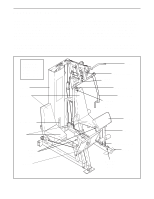
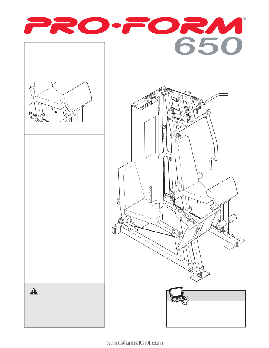
versatile PROFORM® 650 weight manual). For your benefit, read this manual carefully before Before reading further, please review the drawing below using the weight system. If you have additional ques- and familiarize yourself with the parts that are labeled. tions, please call our Customer Service - ProForm 650 | English Manual - Page 5
the weight system, orient all parts exactly as shown in the drawings. Tightening Parts Tighten all parts as you assemble them, unless instructed to do otherwise. Questions? If you have questions after reading the assembly instructions, please call our Customer Service Department toll-free at 1-800 - ProForm 650 | English Manual - Page 6
understood the information on page 5. This brief introduction will save you much more time than it takes to read it. 24 3 33 Open the parts bag labeled "FRAME ASSEMBLY." Press two 2" x 3" Inner Caps (24) into the ends of the Stabilizer (5). Press a 2" x 3" Inner Cap and a 2" Square Inner Cap (33 - ProForm 650 | English Manual - Page 7
Bumpers and the Stabilizer. Attach the indicated Weight Guide (23) to the Stabilizer (5) with a 3/8" x 2 1/2" Bolt (54), two 5/8" x 1/2" Bushings (42), two 3/8" Washers (55), and a 3/8" Nylon Jamnut (63). 23 55 63 42 19 5 42 4. Open the parts bag labeled "Weight Inserts." 4 See the inset - ProForm 650 | English Manual - Page 8
the holes. Thread a 3/8" Nylon 50 Locknut (50) onto the lower Bolt. Do not thread a Locknut onto the upper Bolt yet. Attach the Weight Guides (23) to the Top Frame (1) with two 3/8" x 1 3/4" Bolts (60) and two 3/8" Nylon Locknuts (50). Welded Tubes 6. Press a 2" x 3" Inner Cap (24) into the - ProForm 650 | English Manual - Page 9
Arm Assembly 9 9. Open the parts bags labeled "ARM ASSEMBLY." Attach the Rear and Forward Leg Press Uprights (97, 98) to the Leg Press Base (84) with two 3/8" x 3 1/4" Bolts (87) and - ProForm 650 | English Manual - Page 10
13. Attach the Leg Lever Lock (11) to the front leg of 13 the Base (8) with a 5/16" x 3" Bolt (78), three 5/16" Washers (80), and a 5/16" Nylon Locknut (81). Do not overtighten the Nylon Locknut; the Leg Lever Lock must pivot easily. Front Leg 8 80 78 11 14. Press two 2" Square Inner Caps ( - ProForm 650 | English Manual - Page 11
Cable Assembly 16. Open the parts bags labeled "CABLE ASSEMBLY" and "4 PULLEYS." Refer to the CABLE DIAGRAM on page 21 to identify the cables and for correct cable routing. Locate the - ProForm 650 | English Manual - Page 12
20. Wrap the Leg Press Cable (76) around a 4" 20 Pulley (35). Attach the Pulley and a Cable Trap (44) to the bracket on the Stabilizer (5) with a 3/8" x 2" Bolt (62) and a 3/8" Nylon Locknut (50). Be sure that the Cable Trap (44) is positioned to hold the Cable in the pulley groove. 62 35 76 - ProForm 650 | English Manual - Page 13
23. Remove the upper 3/8" x 3" Bolt (45) from the Top Frame (1) and the Main Upright (3). Route the High Cable (73) around a 4" Pulley (35) and down through the indicated slot in the Main Upright (3), as shown. Attach the Pulley inside the slot with a 3/8" x 2 1/2" Bolt (54), two 3/8" Washers (55), - ProForm 650 | English Manual - Page 14
26. Wrap the High Cable (73) around a 4" Pulley (35). 26 Attach the Pulley inside the slot in the Main Upright (3) with a 3/8" x 2 1/2" Bolt (54), two 3/8" Washers (55), two 5/8" x 1/2" Bushings (42), and a 3/8" Nylon Jamnut (63). 3 35 73 63 42 55 54 42 55 27. Disassemble the pre- - ProForm 650 | English Manual - Page 15
29. Wrap the High Cable (73) around a 4" Pulley 29 (35). Attach the Pulley and a Cable Trap (44) to the top hole in the Pulley Bracket (91) attached to the Leg Press Cable (76), with a 3/8" x 1 3/4" Bolt (60) and a 3/8" Nylon Jamnut (63). 35 30. Route the High Cable (73) up through the next - ProForm 650 | English Manual - Page 16
33. Attach a 4" Pulley (35) over the Low Cable (72), 33 inside the front leg of the Base (8) with a 3/8" x 2 1/2" Bolt (54), two 3/8" Washers (55), two 5/8" x 1/2" Bushings (42), and a 3/8" Nylon Jamnut (63). 8 72 35 34. Route the Low Cable (72) through the indicated slot in the Main Upright - ProForm 650 | English Manual - Page 17
that the cables and pulleys move smoothly. Thread the 1/2" Plain Nut (68) part way onto the bolt at the end of the High Cable (73). Place Nut (68) against the 1 1/2" Washer (40). Seat Assembly 39 39. Open the parts bag labeled "ARM AND SEAT ASSEMBLY." Attach a Seat (13) to the Seat Upright (37 - ProForm 650 | English Manual - Page 18
40. Insert a 1/4" x 3 3/4" Carriage Bolt (43) into each Backrest Plate (27). Attach the Backrest Plates to the Backrest (41) with four 1/4" x 3/4" Bolts (17). 40 71 25 17 27 43 41 Attach the Backrest (41) to the Main Upright (3) with the two 1/4" x 3 3/4" Carriage Bolts (43), two 1/4" Washers ( - ProForm 650 | English Manual - Page 19
44. Press two 3/4" Round Inner Caps (34) into the 44 ends of the remaining Pad Tube (28). Slide the Pad Tube (28) through the hole in the Main Upright (3). Slide two Foam Pads (30) onto the ends of the Pad Tube. 30 34 30 34 28 3 45. Slide the two Tinnerman Clips (38) down over the 45 slots - ProForm 650 | English Manual - Page 20
the remaining parts will be explained in ADJUSTMENTS, beginning on page 22 of this manual. Before using the weight system, pull each cable a few times to make sure that the cables move smoothly over the pulleys. If one of the cables does not move smoothly, find and correct the problem. IMPORTANT: If - ProForm 650 | English Manual - Page 21
CABLE DIAGRAM The diagram below shows the proper routing of the Low Cable (72), the High Cable (73), and the Leg Press Cable (76). The numbers show the correct route for each cable. Make sure that the cables are routed correctly, that the pulleys move smoothly, and that the cable traps do not touch - ProForm 650 | English Manual - Page 22
The instructions below describe how each part of the weight system can be adjusted. Refer to the exercise guide accompanying this manual to the weight setting. Use the WEIGHT RESISTANCE CHART on page 24 of this manual to find the approximate amount of resistance at each weight station. ATTACHING THE - ProForm 650 | English Manual - Page 23
CONVERTING THE PRESS/FLY ARMS To use the Press/Fly Arms (46, 49) as fly arms, insert the Adjustment Pins (20) into the inner holes in the Press Frame (12) (see inset drawing A). To use the Press/Fly Arms (46, 49) as press arms, insert the Adjustment Pins (20) into the outer holes in the Press - ProForm 650 | English Manual - Page 24
: The actual resistance at each station may vary due to differences in individual weight plates as well as friction between the cables, pulleys, and weight guides. Weight Plates Top 1 2 3 4 5 6 7 8 9 10 11 12 13 14 15 16 17 18 19 Press Arm (lbs.) 24 35 46 57 68 79 90 102 113 - ProForm 650 | English Manual - Page 25
TROUBLESHOOTING AND MAINTENANCE Make sure all parts are properly tightened each time you use the weight system. Replace any worn parts immediately. The weight system can be cleaned using a re-install it. If a cable needs to be replaced, refer to the back cover of this manual. 25 35 44 73 63 91 60 - ProForm 650 | English Manual - Page 26
30 minutes, resting for a maximum of 30 seconds between sets. Cross Training Cross training is an efficient way to get a complete and well-balanced appropriate parts of the body. Exercising in an uncontrolled manner will leave you feeling exhausted. On the exercise guide accompanying this manual - ProForm 650 | English Manual - Page 27
at the end of every month. Remember, the key to achieving the greatest results is to make exercise a regular and enjoyable part of your everyday life. MUSCLE CHART A. Sternomastoid (neck) B. Pectoralis Major (chest) A C. Biceps (front of arm) B D. Obliques (waist) E. Brachioradials (forearm - ProForm 650 | English Manual - Page 28
PART IDENTIFICATION CHART-Model No. PFSY69520 R0103A 1/4" Nylon Locknut (25) 5/16" Nylon Jamnut (79) 5/16" Nylon Locknut (81) 3/8" Nylon Jamnut (63) 3/8" Nylon Locknut (50) #8 x 3/4" Screw (32) 1/4" x 3/4" - ProForm 650 | English Manual - Page 29
3/8" x 8 1/2" Bolt (59) 3/8" x 9" Bolt (51) 3/8" x 2 1/2" Bolt (54) 5/16" x 3" Bolt (78) 3/8" x 3" Bolt (45) 3/8" x 3" Carriage Bolt (64) 3/8" x 3 1/4" Bolt (87) 3/8" x 3 1/2" Bolt (22) 3/8" x 3 3/4" Bolt (92) 1/4" x 3 3/4" Carriage Bolt (43) 3/8" x 3 3/4" Carriage Bolt (52) 3/8" x 4" Bolt (65) - ProForm 650 | English Manual - Page 30
1/2" x 1 3/4" Bushing (94) 1/2" x 3/4" Long Bushing (93) 5/8" x 1/4" Bushing (90) 5/8" x 1/2" Bushing (42) 3/4" Round Inner Cap (34) 1" Round Inner Cap (103) 2" Square Inner Cap (33) Cable Clip (69) 2" Round Inner Cap (57) 3/4" x 1/2" Flange Bushing (18) 2" x 3" Inner Cap (24) - ProForm 650 | English Manual - Page 31
Adjustment Pin Curl Pad 3/8" x 3 1/2" Bolt Weight Guide 2" x 3" Inner Cap 1/4" Nylon Locknut Weight Manual Note: "#" indicates a non-illustrated part. Specifications are subject to change without notice. See the back cover of the user's manual for information about ordering replacement parts - ProForm 650 | English Manual - Page 32
23 25 17 71 55 63 42 66 73 68 40 36 47 16 93 2 32 70 17 17 53 9 101 95 33 74 101 25 17 86 95 25 17 53 17 71 17 102 77 26 56 32 61 42 35 77 39 35 42 35 42 42 55 63 55 63 63 55 50 60 42 15 1 42 35 42 35 45 54 42 55 54 50 42 55 42 55 73 54 55 14 55 63 42 35 63 42 42 55 54 63 - ProForm 650 | English Manual - Page 33
The NAME of the product (PROFORM® 650 weight system) 3. The SERIAL NUMBER of the product (see the front cover of this manual) 4. The KEY NUMBER and DESCRIPTION of the part(s) (see the PART LIST and EXPLODED DRAWING in the center of this manual). LIMITED WARRANTY ICON Health & Fitness, Inc. (ICON
-
 1
1 -
 2
2 -
 3
3 -
 4
4 -
 5
5 -
 6
6 -
 7
7 -
8
-
9
-
10
-
11
-
12
-
13
-
14
-
15
-
16
-
17
-
18
-
19
-
20
-
21
-
22
-
23
-
24
-
25
-
26
-
27
-
28
-
29
-
30
-
31
-
32
-
33
 |
 |
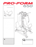
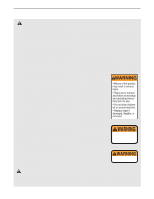
CAUTION
Read all precautions and instruc-
tions in this manual before using
this equipment. Save this manual
for future reference.
Model No. PFSY69520
Serial No.
The serial number is found in the
location shown below. Write the
serial number in the space above.
Visit our website at
www.proform.com
new products, prizes,
fitness tips, and much more!
USER’S MANUAL
QUESTIONS?
As a manufacturer, we are com-
mitted to providing complete
customer satisfaction. If you
have questions, or if there are
missing parts, we will guarantee
complete satisfaction through
direct assistance from our factory.
TO AVOID DELAYS, PLEASE
CALL DIRECT TO OUR TOLL-
FREE CUSTOMER HOT LINE.
The trained technicians on our
customer hot line will provide
immediate assistance, free of
charge.
CUSTOMER HOT LINE:
1-800-999-3756
Mon.–Fri., 6 a.m.–6 p.m. MST
Serial Number Decal