ProForm 650 English Manual - Page 17
Seat Assembly
 |
View all ProForm 650 manuals
Add to My Manuals
Save this manual to your list of manuals |
Page 17 highlights
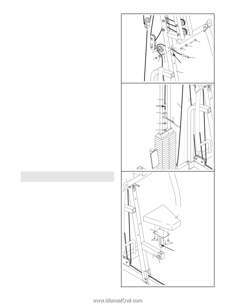
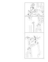
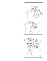
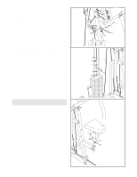
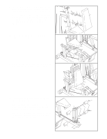
37. Route the end of the Low Cable (72) through the 37 indicated slot in the Main Upright (3). Wrap the Low Cable (72) around a 4" Pulley (35). Attach the Pulley inside the slot in the Main Upright (3) with a 3/8" x 2 1/2" Bolt (54), two 3/8" Washers (55), two 5/8" x 1/2" Bushings (42), and a 3/8" Nylon Jamnut (63). 38. IMPORTANT: Follow the cables from end to 38 end; make sure that they are in the grooves of the pulleys and that the cables and pulleys move smoothly. Thread the 1/2" Plain Nut (68) part way onto the bolt at the end of the High Cable (73). Place the 1 1/2" Washer (40) on top of the Weight Tube (36). Insert the bolt on the High Cable (73) through the ring on the Weight Pin (39) and into the threaded hole in the Weight Tube (36). Tighten the bolt into the Weight Tube until the Cables (73, 72, 76) are tight. Tighten the 1/2" Plain Nut (68) against the 1 1/2" Washer (40). Seat Assembly 39 39. Open the parts bag labeled "ARM AND SEAT ASSEMBLY." Attach a Seat (13) to the Seat Upright (37) with four 1/4" x 3/4" Bolts (17). Turn the Adjustment Knob (9) on the Main Upright (3) counterclockwise to loosen it and pull it out as far as possible. Slide the Seat Upright (37) into the Main Upright. Release the Knob and let it engage one of the adjustment holes in the Seat Upright. Retighten the Knob. 35 63 55 42 54 55 42 72 Slot 3 73 Bolt 68 40 36 76 72 39 13 37 17 3 9 17 Adjustment Holes 17
-
 1
1 -
2
-
3
-
4
-
5
-
6
-
7
-
8
-
9
-
10
-
11
-
 12
12 -
 13
13 -
 14
14 -
 15
15 -
 16
16 -
 17
17 -
 18
18 -
 19
19 -
 20
20 -
 21
21 -
 22
22 -
23
-
24
-
25
-
26
-
27
-
28
-
29
-
30
-
31
-
32
-
33
 |
 |