Reebok Crosswalk V 7.9 Treadmill English Manual - Page 10
Resistance Knob.
 |
View all Reebok Crosswalk V 7.9 Treadmill manuals
Add to My Manuals
Save this manual to your list of manuals |
Page 10 highlights
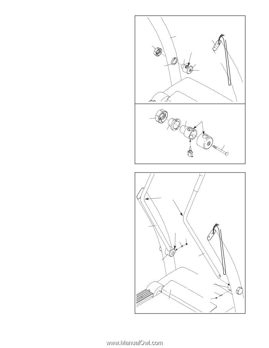
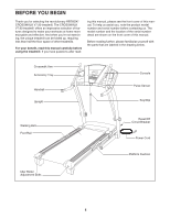
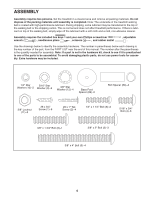
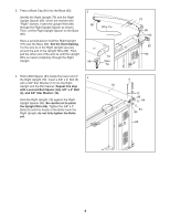
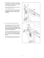
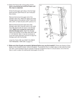
7. Remove the Resistance Knob (110) from a resistance mechanism. Make sure that the 3/8" x 4 3/4" Bolt (112) stays inside the resistance mechanism and that the resistance mechanism does not come apart. Note: See the lower drawing to reassemble the resistance mechanism if necessary. Apply a small amount of the included grease around the Resistance Cone (108) and the Upright Insert (111). Insert the Resistance Cone (108) into the Upright Insert (111) in the Left Upright (77), with the two large holes on top as shown. Then, tighten the Resistance Knob (110) onto the 3/8" x 4 3/4" Bolt (112). Do not fully tighten the Resistance Knob. Attach the other resistance mechanism to the Right Upright (79) as described above. 7 110 111 77 79 Large Holes 108 Resistance Mechanism 112 110 111 Large 108 Holes 112 8. Insert the end of a Crosswalk Arm (98) into the hole in the top of a resistance mechanism. Make sure that the bend in the Crosswalk Arm is positioned as shown. Tighten a #8 x 3/4" Screw (1) into the resistance mechanism and the Crosswalk Arm (98) from the direction shown. Then, press a Small Cap (34) into the hole for the Screw. Attach the other Crosswalk Arm (98) as described above. Carefully lower the Crosswalk Arms (98) down toward the Walking Belt (42). 8 Bend 98 Hole 34 1 Resistance Mechanism 42 98 Resistance Mechanism 1 34 10
-
 1
1 -
2
-
3
-
4
-
 5
5 -
 6
6 -
 7
7 -
 8
8 -
 9
9 -
 10
10 -
 11
11 -
 12
12 -
 13
13 -
 14
14 -
 15
15 -
16
-
17
-
18
-
19
-
20
-
21
-
22
-
23
-
24
-
25
-
26
-
27
-
28
-
29
-
30
-
31
-
32
 |
 |