Reebok Trainer Rx 3.5 Bike English Manual - Page 26
Maintenance And Troubleshooting
 |
View all Reebok Trainer Rx 3.5 Bike manuals
Add to My Manuals
Save this manual to your list of manuals |
Page 26 highlights
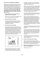
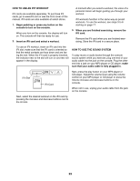
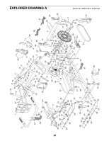
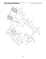
MAINTENANCE AND TROUBLESHOOTING Inspect and tighten all parts of the exercise bike regularly. Replace any worn parts immediately. To clean the exercise bike, use a damp cloth and a small amount of mild soap. IMPORTANT: To avoid damaging the console, keep liquids away from the console and keep the console out of direct sunlight. CONSOLE TROUBLESHOOTING Most console problems are the result of low batteries. See assembly step 7 on page 9 for battery replacement instructions. If the handgrip heart rate monitor does not function properly, see step 5 on page 16. Repeat these actions until the console displays correct feedback. When the reed switch is correctly adjusted, reattach the shield cover. HOW TO ADJUST THE DRIVE BELT If the pedals slip while you are pedaling, even when the resistance is adjusted to the highest setting, the drive belt may need to be adjusted. If you are using the optional power adapter, unplug it. Next, using an adjustable wrench, turn the right pedal counterclockwise and remove it. Using a flat screwdriver, release the tabs on the Shield Cover (5) and slide the Shield Cover upward. HOW TO ADJUST THE REED SWITCH 5 If the console does not display correct feedback, the reed switch should be adjusted. If you are using the optional power adapter, unplug it. Using a flat screwdriver, release the tabs on the Shield Cover (5) and pull the Shield Cover upward. 22 34 92 52 46 78 84 5 58 Locate the Reed Switch (46). Turn the Pulley (58) until a Magnet (52) is aligned with the Reed Switch. Next, loosen, but do not remove, the indicated M4 x 13mm Flange Screw (92). Slide the Reed Switch slightly closer to or away from the Magnet, and then retighten the Screw. Turn the Pulley for a moment. Remove all of the screws from the Left Front Shield (22) and the Right Front Shield (not shown); there are three sizes of screws—-note which size of screw you remove from each hole. Then, gently pull the Right Front Shield away from the frame. Next, loosen the M6 x 20mm Hex Screw (78). Tighten the M10 x 50mm Hex Screw (84) until the Drive Belt (34) is tight. Then, tighten the M6 x 20mm Hex Screw. Finally, reattach the front shields, the shield cover, and the right pedal. 26
-
 1
1 -
2
-
3
-
4
-
5
-
6
-
7
-
8
-
9
-
10
-
11
-
12
-
13
-
14
-
15
-
16
-
17
-
18
-
19
-
20
-
 21
21 -
 22
22 -
 23
23 -
 24
24 -
 25
25 -
 26
26 -
 27
27 -
 28
28 -
 29
29 -
 30
30 -
 31
31 -
32
 |
 |
