Ryobi RLS1351 Operation Manual - Page 10
Assembly - replacement blade
 |
View all Ryobi RLS1351 manuals
Add to My Manuals
Save this manual to your list of manuals |
Page 10 highlights
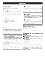
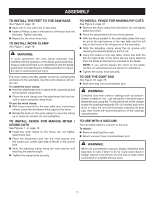
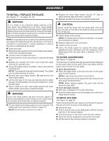
ASSEMBLY LOOSE PARTS LIST See Figure 2, page 17. The following items are included with the saw: Key No. Description Qty. A Saw Handle 1 B Screws 2 C Blade Wrench 1 D Screws 4 E Feet 4 F Push Stick 1 G Work Clamp 1 H Fence 1 I Dust Bag 1 J Screws 2 K Foot/Blade Wrench Holder 1 Operator's Manual (not shown 1 UNPACKING This product requires assembly. Carefully lift saw from carton and place on a level work surface. WARNING: Do not use this product if any parts on the Loose Parts List are already assembled to your product when you unpack it. Parts on this list are not assembled to the product by the manufacturer and require customer installation. Use of a product that may have been improperly assembled could result in serious personal injury. Inspect the tool carefully to make sure no breakage or damage occurred during shipping. Do not discard the packing material until you have carefully inspected and satisfactorily operated the product. The saw is factory set for accurate cutting. After assembling it, check for accuracy. If shipping has influenced the settings, take to an authorized service center. If any parts are damaged or missing, please call 1-800-525-2579 for assistance. Warning: If any parts are damaged or missing do not operate this product until the parts are replaced. Use of this product with damaged or missing parts could result in serious personal injury. warning: Do not attempt to modify this product or create accessories not recommended for use with this tool. Any such alteration or modification is misuse and could result in a hazardous condition leading to possible serious personal injury. WARNING: Do not connect to power supply until assembly is complete. Failure to comply could result in accidental starting and possible serious personal injury. WARNING: Never stand directly in line with the blade or allow hands to come closer than 3 in. to the blade. Do not reach over or across the blade. Failure to heed this warning can result in serious personal injury. NOTE: No adjustments that can made to this tool except by an authorized service center. TO install the saw handle See Figure 3, page 18. Position the saw handle over the holes in the saw hous- ing (straight side of the handle to the back). Secure saw handle in place using Phillips screws. TO install the Foot/Blade Wrench holder See Figure 4, page 18. Align holes in foot/blade wrench holder with holes under the saw base. Insert Phillips screw through the foot and into the base. Tighten securely. TO attach saw to mounting boards or work bench See Figure 5, page 18. The saw should be mounted to a firm supporting surface such as a workbench or mounting boards. Four bolt holes have been provided in the feet for this purpose. Secure using bolts and washers (not included). Bolts should be of sufficient length to accommodate the saw base, washers, and the thickness of the workbench or mounting board. Tighten bolts securely. 10
-
 1
1 -
2
-
3
-
4
-
 5
5 -
 6
6 -
 7
7 -
 8
8 -
 9
9 -
 10
10 -
 11
11 -
 12
12 -
 13
13 -
 14
14 -
 15
15 -
16
-
17
-
18
-
19
-
20
-
21
-
22
-
23
-
24
-
25
-
26
-
27
-
28
-
29
-
30
-
31
-
32
-
33
-
34
-
35
-
36
-
37
-
38
-
39
-
40
-
41
-
42
-
43
-
44
-
45
-
46
-
47
-
48
-
49
-
50
-
51
-
52
-
53
-
54
-
55
-
56
 |
 |