Samsung HT-TXQ120 Quick Guide (easy Manual) (ver.1.0) (English) - Page 5
Description, Main unit, Subwoofer, Accessories - hdmi
 |
UPC - 036725616660
View all Samsung HT-TXQ120 manuals
Add to My Manuals
Save this manual to your list of manuals |
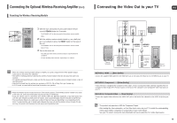
Page 5 highlights
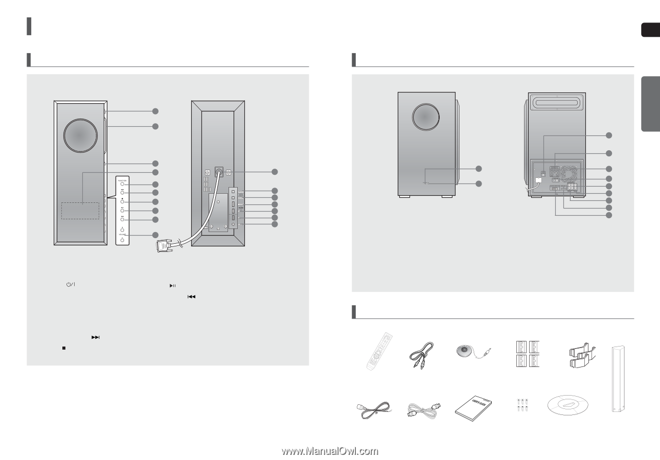
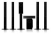
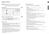
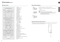
Description Main unit 1 2 3 4 5 6 7 8 9 10 11 12 13 14 15 16 17 1 Power ( ) button 2 Disc Insert Hole 3 Eject button 4 Display panel 5 Function button 6 Tuning Up & Skip ( ) button 7 Stop ( ) button 8 Play/Pause ( ) button 9 Tuning Down & Skip ( ) button 10 Volume Control buttons 11 System Connector cable 12 External Digital Optical Input Connector 2 Use this to connect external equipment capable of digital output. 13 External Digital Optical Input Connector 1 Use this to connect external equipment capable of digital output. 14 HDMI OUT Jack 15 HDMI IN Jack 16 USB Port 17 Headphone Jack 8 Subwoofer ENG PREPARATION 1 Standby indicator 2 Power on indicator 3 Auto Sound Calibration Input Connector 4 5.1 Channel Speaker Output Connectors 3 4 1 5 6 2 7 8 9 10 11 5 Cooling Fan 6 FM 75Ω COAXIAL Jack 7 Component Video Output Jacks Connect a TV with Component video inputs to these jacks. 8 Video Output Jack Connect your TV's Video Input jack (VIDEO IN) to the VIDEO OUT Jack on this unit. 9 External Digital Optical Input Jack 10 TX Card Connection (WIRELESS) 11 System Connector Accessories Auto Sound Calibration Core (4EA) Remote Control Video Cable (AH59-01643Z) (AH39-40001V) Microphone (AH59-01183D) (Toroidal Ferrite Core) (3301-000144) Cable Holder (3EA) (AH61-02393A) FM Antenna (AH42-00017A) HDMI Cable (AH39-00923A) User's Manual (AH68-01959R) Screw (6EA) Stand base (AH64-01106Q) (AH97-01906A) STAND (AH97-01905A) 9
-
 1
1 -
 2
2 -
 3
3 -
 4
4 -
 5
5 -
 6
6 -
 7
7 -
 8
8 -
 9
9 -
 10
10 -
 11
11 -
12
-
13
-
14
-
15
-
16
-
17
-
18
-
19
-
20
-
21
-
22
-
23
-
24
-
25
-
26
-
27
-
28
-
29
-
30
-
31
-
32
-
33
-
34
-
35
-
36
 |
 |