Samsung SPH700AE User Manual (ENGLISH) - Page 61
Connecting to PC, PC Video Cable, pin signal, DVI-D, supports only digital signals
 |
UPC - 036725240216
View all Samsung SPH700AE manuals
Add to My Manuals
Save this manual to your list of manuals |
Page 61 highlights
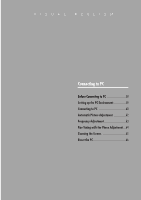
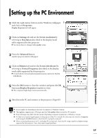
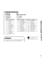
Connecting to PC Pin Configuration of PC Video Port Plug PC Video Cable (15-pin signal) DVI-D (supports only digital signals) Pin No. 1 2 3 4 5 6 7 8 9 10 11 12 13 14 15 PC Input Red (R) Green (G) Blue (B) Ground Ground (DDC) Red (R) Ground Green (G) Ground Blue (B) Ground Reserved Ground Sync Ground Data (DDC) Horizontal Sync Vertical Sync Clock (DDC) Pin No. 1 2 3 4 5 6 7 8 9 10 11 12 Signal T.M.D.S. DATA2T.M.D.S. DATA2+ T.M.D.S. DATA2/4 Shield T.M.D.S. DATA4T.M.D.S. DATA4+ Clock (DDC) Data (DDC) No Connection T.M.D.S. DATA1T.M.D.S. DATA1+ T.M.D.S. DATA1/3 Shield T.M.D.S. DATA3- Pin No. 13 14 15 16 17 18 19 20 21 22 23 24 Signal T.M.D.S. DATA3+ +5V Power Ground for 5V Hot Plug Detect T.M.D.S. DATA0T.M.D.S. DATA0+ T.M.D.S. DATA0/5 Shield T.M.D.S. DATA5T.M.D.S. DATA5+ T.M.D.S. Clock Shield T.M.D.S. Clock+ T.M.D.S. Clock- VESA Plug & Play This appliance supports VESA Plug & Play and recognizes connection to PC automatically. DVI-D cable does not support CAUTION analog RGB signals. Connecting to PC 61
-
 1
1 -
2
-
3
-
4
-
5
-
6
-
7
-
8
-
9
-
10
-
11
-
12
-
13
-
14
-
15
-
16
-
17
-
18
-
19
-
20
-
21
-
22
-
23
-
24
-
25
-
26
-
27
-
28
-
29
-
30
-
31
-
32
-
33
-
34
-
35
-
36
-
37
-
38
-
39
-
40
-
41
-
42
-
43
-
44
-
45
-
46
-
47
-
48
-
49
-
50
-
51
-
52
-
53
-
54
-
55
-
 56
56 -
 57
57 -
 58
58 -
 59
59 -
 60
60 -
 61
61 -
 62
62 -
 63
63 -
 64
64 -
 65
65 -
 66
66 -
67
-
68
-
69
-
70
-
71
-
72
-
73
-
74
-
75
-
76
-
77
-
78
-
79
-
80
-
81
-
82
-
83
-
84
 |
 |