Sanyo VCC-HD5400 VCC-HD5400 Setup and Summary Manual - Page 10
Installation
 |
UPC - 086483075698
View all Sanyo VCC-HD5400 manuals
Add to My Manuals
Save this manual to your list of manuals |
Page 10 highlights
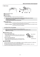
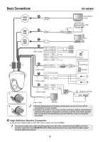
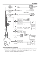
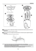
Installation ⴺ Using the supplied • Pull out the cables pattern sheet, drill from the ceiling. the holes for the cables and screws. ⴼ Attach the supplied mounting plate to the ceiling using commercially-available screws. (Screw: M4/No. 8 or equivalent) Length: 40 mm/1.6 in or more, Head: φ 8.3 mm/0.3 in • Loosen the screw (A) and remove the cable holder (B). (B) (A) ⴾ Hook the safety cable attached on the camera base to the mounting plate. ⵀ Connect the cables from the ceiling to the camera cables. ( Page 5 "Basic Connections") ᶃ After connecting each of the terminals (LAN, USB, HDMI), put the cable holder (B) back to its original position so as to hold all the cables in place, and tighten the screw (A). ᶄ Using the supplied fixer (C), tidy the wiring by binding all the cables to make the installation easier. (B) (C) (A) After binding, cut off the excess portion of the fixer. When routing cables through the side face of the camera Remove the wire gutter cover (AA). (AA) (C) If you use a USB cable or an HDMI cable, secure it along with the LAN cable using the supplied fixer (C) so that the cables don't easily come off. When you route the cables after installing the camera, be sure to carefully handle the cables so as not to strongly pull them. 9
-
 1
1 -
2
-
3
-
4
-
 5
5 -
 6
6 -
 7
7 -
 8
8 -
 9
9 -
 10
10 -
 11
11 -
 12
12 -
 13
13 -
 14
14 -
 15
15 -
16
-
17
 |
 |
