Sanyo VCC-HD5400 VCC-HD5400 Setup and Summary Manual - Page 12
Control/Address Settings
 |
UPC - 086483075698
View all Sanyo VCC-HD5400 manuals
Add to My Manuals
Save this manual to your list of manuals |
Page 12 highlights
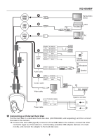
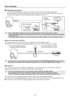
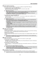
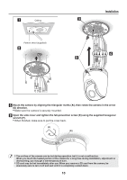
Control/Address Settings When you connect the camera to a controller, it is necessary to configure the interface board control switch and address switch. ■ Control switch This is used to configure transmission rate and protocol, etc. • Switches 2 and 3 are not used. • Settings in bold typeface in the table below show the factory default configurations. ⁞ Baud Rate Configure the transmission rate of connected devices to the transmission rate of the camera. Transmission Rate 2400 4800 9600 19200 Switch 6 OFF ON OFF ON Switch 5 OFF OFF ON ON ON 6 54321 ⁞ When protocol is set to "PELCO", set to 2400. Protocol Select the protocol for controlling the camera. Protocol SSP (SANYO) PELCO Switch 4 OFF ON Corresponding Protocol Automatic switching between Sanyo SSP and high speed SSP Automatic switching between PELCO-D and PELCO-P Terminator When you connect multiple cameras, set the terminator setting (Switch 1) of the final device to "ON" and all other devices to "OFF". ■ Address switch If you use the RS485 communication mode, assign a unique address (camera No.) to each camera. Configure the address by setting the dip switches to "ON" and "OFF". For further information, refer to the "Address Settings Table" on the next page. ON 1 234 5 67 8 11
-
 1
1 -
2
-
3
-
4
-
5
-
6
-
 7
7 -
 8
8 -
 9
9 -
 10
10 -
 11
11 -
 12
12 -
 13
13 -
 14
14 -
 15
15 -
 16
16 -
 17
17
 |
 |
