Sanyo VCC-HD5400 VCC-HD5400 Setup and Summary Manual - Page 9
Alarm Cable Connection, Audio Jack Connection, Power Connection, Connection of controller
 |
UPC - 086483075698
View all Sanyo VCC-HD5400 manuals
Add to My Manuals
Save this manual to your list of manuals |
Page 9 highlights
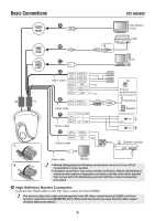
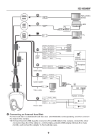
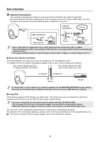
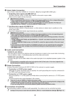
Basic Connections ⦊ Alarm Cable Connection Use a thicker cable than 24AWG for connection. (Maximum length 600 m/656 yds.) ᶃ Outputting alarm signals (ALARM OUT1-2) Connect a buzzer, lamp, or other alarm device to the alarm output cable. Alarm can be output via two channels. ( Electronic manual) • After connecting an alarm device, configure the output conditions for the corresponding alarm output cable via network operation on the ALARM SETTINGS screen. • Configuration of alarm output terminal is also possible via remote operation. For that, set [ALARM OUT] to "REMOTE" on the ALARM SETTINGS screen. ᶄ Inputting alarm signals (ALARM IN1-4) Connect an alarm switch, infrared sensor, or other device to detect alarm conditions to the alarm input cable. Up to four independent alarm input channels are available. ( Electronic manual) • After connecting an alarm device, configure the input conditions for the corresponding alarm input cable via network operation on the ALARM SETTINGS screen. • To use the alarm input terminals as color/black-and-white mode switching terminals, follow the steps below. • Under CAMERA SETTINGS, set [DAY/NIGHT] to "COLOR" and select the cable you want to use in [EXT ALARM]. • On the ALARM SETTINGS screen, in [POLARITY], select the signal polarity of the alarm input terminal. • If you connect an external switch to ALARM IN1 terminal, you can specify time by controlling the switch. In this case, configure the [CLOCK IN] setting via network operation on CLOCK SETTINGS screen. ⦋ Audio Jack Connection • AUDIO IN Jack (White) Use this jack to connect an optional external microphone to listen to the sound while monitoring the surveillance video, or simultaneously record the video and sound. • AUDIO OUT Jack (Black) Connect this jack via an audio cable to the audio input jack of an amplified speaker system or the monitor. This terminal is compatible with mono microphone with 3.5-mm jack or line mono signals (only the left channel in cases of stereo signals). ⦌ Power Connection Connect the power terminals (24 VAC/12 VDC) of the camera to a power supply. ᶃ Connection to 24 VAC power supply Although the power terminals have no polarity, the earth grounding wire must be connected to the GND (earth grounding) terminal. ᶄ Connection to 12 VDC power supply Note the polarity (+/-) of the power terminals when connecting the camera to a 12 VDC power supply. Incorrect polarity may cause damage to the camera. • Be sure to use an 18AWG or thicker wire power cable. • If you must use a long power cable, determine the cable type by ensuring that the voltage at the 24 VAC/12 VDC terminal is within the operating range of the camera. • If you are using PoE, do not use the camera's power terminals (24 VAC/12 VDC). ⦍ Connection of controller By connecting a system controller (sold separately), the camera can be controlled remotely. Configure the protocol, baud rate and address. (Refer to "Control/Address Settings" Page 11). 8
-
 1
1 -
2
-
3
-
 4
4 -
 5
5 -
 6
6 -
 7
7 -
 8
8 -
 9
9 -
 10
10 -
 11
11 -
 12
12 -
 13
13 -
 14
14 -
15
-
16
-
17
 |
 |
