Sanyo VCC-HD5400 VCC-HD5400 Setup and Summary Manual - Page 3
Name and Function of Each Component - hd
 |
UPC - 086483075698
View all Sanyo VCC-HD5400 manuals
Add to My Manuals
Save this manual to your list of manuals |
Page 3 highlights
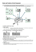
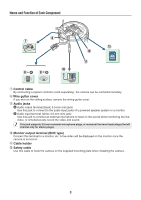
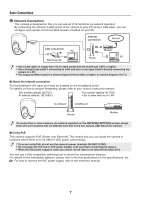
Name and Function of Each Component For the cable type, see the "cable label" attached to the cable bundle. For the detailed connection procedure, refer to the "Basic Connections" section. ( Page 5) ᶃ ᶆ ᶇ 24 VAC GND ~ ~ 12 VDC + ᶅ ᶄ ᶈ ᶃ 24 VAC /12 VDC Power cable ᶄ Alarm cables • Alarm input cable: Connect an external switch, infrared sensor, or other device to detect alarm conditions such as the entry of an intruder. • Alarm output cable: Connect a buzzer, lamp, or other alarm device. ᶅ Dip switch ( Page 11 "Control/Address Settings") ⦇ ⦈ ON ON 6 54321 1 234 5 67 8 ⦇ Control switch: Use this switch to configure the baud rate and protocol settings. ⦈ Address switch: Use this switch to configure the camera control address. ᶆ Network Socket (LAN: RJ-45, PoE) ᶇ EX-HDD terminal (USB type) To record video on an external hard disk drive, you must install a 2.5" hard disk drive (SATA) in the dedicated hard disk case (VA-HDC4000) which is sold separately and then connect the hard disk drive case. ᶈ HDMI Connector The terminal outputs super-fine HD (High Definition) video signal. Use the terminal to connect a high-definition monitor with HDMI interface. 2
-
 1
1 -
 2
2 -
 3
3 -
 4
4 -
 5
5 -
 6
6 -
 7
7 -
 8
8 -
 9
9 -
10
-
11
-
12
-
13
-
14
-
15
-
16
-
17
 |
 |
