Sharp PN-A601 PN-A601 Professional LCD Monitor Operation Manual - Page 13
External speaker terminals, Audio2 input terminals
 |
View all Sharp PN-A601 manuals
Add to My Manuals
Save this manual to your list of manuals |
Page 13 highlights
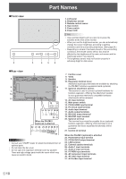
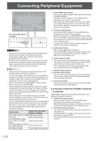
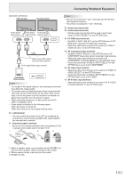
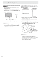
Connecting Peripheral Equipment (Example connection) First monitor Second monitor PC/AV DVI-D input terminal PC/AV DVI-D PC/AV DVI-D output terminal input terminal Digital signal (DVI) cables (commercially available) To PC digital RGB output terminal shows the signal flow TIPS • The length of the signal cables or surrounding environment may affect the image quality. • The screen may not display properly when using terminals other than PC DVI-D/AV DVI-D for the input mode. In this case, turn off the power to all the monitors connected in a daisy chain and then turn the power on again. • When connecting monitors in a daisy chain set AUTO INPUT CHANGE to OFF. • Video output is disabled in the following cases: When the power is turned off When the monitor is in input signal waiting mode 10. LAN terminal • You can control the monitor from a PC on a network by connecting a commercially available LAN cable between this terminal and a network. 11. External speaker terminals • Be sure to use external speakers with an impedance of 6 Ω or greater and a rated input of at least 10 W. 1 2 3 Approx. 3-15/16 inch (10 cm) TIPS • Be sure to connect the + and - terminals and the left and right speakers properly. • Avoid short circuiting the + and - terminals. 12. Audio1 input terminals 13. Audio2 input terminals • Set the audio input terminal to be used in each input mode in AUDIO SELECT on the OPTION menu. 14. PC RGB input terminals • Set BNC of INPUT SELECT on the OPTION menu to PC RGB when using the PC RGB input terminals. • Select the audio input terminal to be used in PC RGB of AUDIO SELECT on the OPTION menu. 15. AV component input terminals • Set BNC of INPUT SELECT on the OPTION menu to AV COMPONENT when using the AV component input terminals. • Select the audio input terminal to be used in AV COMPONENT of AUDIO SELECT on the OPTION menu. • Cannot be used when D-SUB in INPUT SELECT on the OPTION menu is set to AV COMPONENT. 16. AV video input terminal • Select the audio input terminal to be used in AV VIDEO of AUDIO SELECT on the OPTION menu. • Cannot be used when D-SUB in INPUT SELECT on the OPTION menu is set to AV VIDEO. 17. AV S-video input terminal • Select the audio input terminal to be used in AV S-VIDEO of AUDIO SELECT on the OPTION menu. 1. Attach a speaker cable core (included with the PN-ZB01) to the end of the speaker cable connected to the monitor. 2. While pushing the tab, insert the tip of the cable. 3. Release the tab. 13 E
-
 1
1 -
2
-
3
-
4
-
5
-
6
-
7
-
 8
8 -
 9
9 -
 10
10 -
 11
11 -
 12
12 -
 13
13 -
 14
14 -
 15
15 -
 16
16 -
 17
17 -
 18
18 -
19
-
20
-
21
-
22
-
23
-
24
-
25
-
26
-
27
-
28
-
29
-
30
-
31
-
32
-
33
-
34
-
35
-
36
-
37
-
38
-
39
-
40
-
41
-
42
-
43
-
44
-
45
-
46
-
47
-
48
-
49
-
50
-
51
-
52
-
53
-
54
-
55
-
56
-
57
-
58
-
59
-
60
 |
 |
