Sony DCRHC21 Operating Guide - Page 48
Dubbing/Editing, Connecting to a VCR or TV - dv cable
 |
UPC - 027242669819
View all Sony DCRHC21 manuals
Add to My Manuals
Save this manual to your list of manuals |
Page 48 highlights
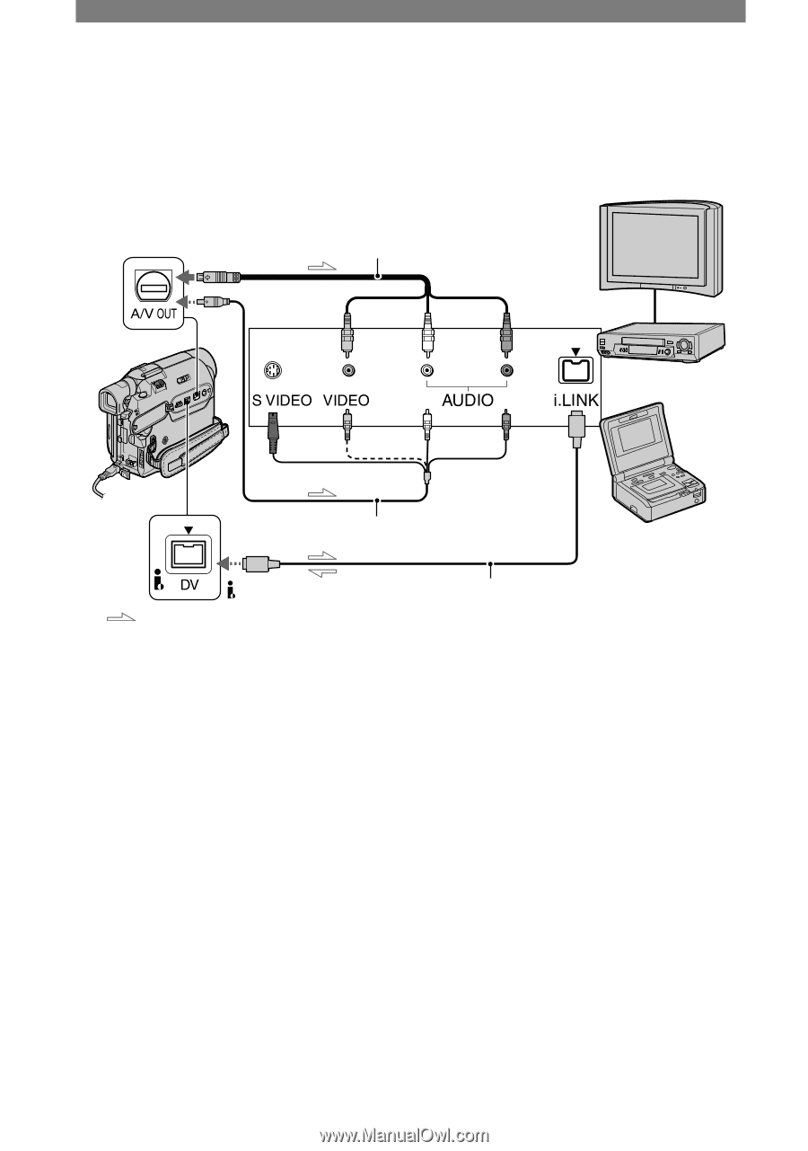
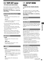
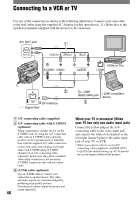
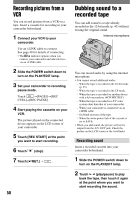
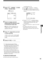
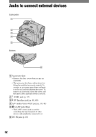
Connecting to a VCR or TV Use any of the connection as shown in the following illustration. Connect your camcorder to the wall outlet using the supplied AC Adaptor for this operation (p. 11). Refer also to the instruction manuals supplied with the devices to be connected. A/V OUT jack 1 (Yellow) (White) (Red) VCRs or TVs 2 DV Interface : Signal flow To i. LINK (IEEE1394) jack 3 i.LINK compliant device A/V connecting cable (supplied) A/V connecting cable with S VIDEO (optional) When connecting to another device via the S VIDEO jack, by using the A/V connecting cable with an S VIDEO cable (optional), pictures can be reproduced more faithfully than with the supplied A/V cable connection. Connect the white and red plugs (left/right audio) and S VIDEO plug (S VIDEO channel) of an A/V connecting cable (optional). In this case, the yellow (standard video) plug connection is not necessary. S VIDEO connection only will not output audio. i.LINK cable (optional) Use an i.LINK cable to connect your camcorder to another device. The video and audio signals are transmitted digitally, producing high quality pictures. Note that you cannot output the picture and sound separately. 48 When your TV is monaural (When your TV has only one audio input jack) Connect the yellow plug of the A/V connecting cable to the video input jack and connect the white (left channel) or the red (right channel) plug to the audio input jack of your TV or VCR. • When you connect a device via an A/V connecting cable (supplied), set [DISP OUT] to [LCD] (the default setting) (p. 47) to prevent the screen display dubbed with pictures.
-
 1
1 -
2
-
3
-
4
-
5
-
6
-
7
-
8
-
9
-
10
-
11
-
12
-
13
-
14
-
15
-
16
-
17
-
18
-
19
-
20
-
21
-
22
-
23
-
24
-
25
-
26
-
27
-
28
-
29
-
30
-
31
-
32
-
33
-
34
-
35
-
36
-
37
-
38
-
39
-
40
-
41
-
42
-
 43
43 -
 44
44 -
 45
45 -
 46
46 -
 47
47 -
 48
48 -
 49
49 -
 50
50 -
 51
51 -
 52
52 -
 53
53 -
54
-
55
-
56
-
57
-
58
-
59
-
60
-
61
-
62
-
63
-
64
-
65
-
66
-
67
-
68
-
69
-
70
-
71
-
72
-
73
-
74
-
75
-
76
-
77
-
78
-
79
-
80
-
81
-
82
-
83
-
84
-
85
-
86
-
87
-
88
-
89
-
90
-
91
-
92
 |
 |