Sony STR-DB830 Service Manual - Page 34
Ic102, Mb90553apf-g-138-bnd Display Controldisplay Board
 |
View all Sony STR-DB830 manuals
Add to My Manuals
Save this manual to your list of manuals |
Page 34 highlights
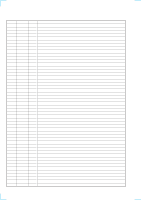
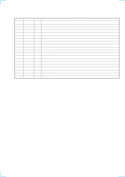
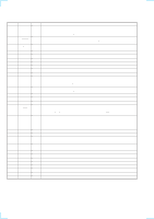
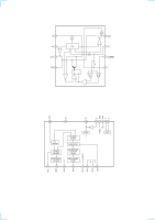
IC102 MB90553APF-G-138-BND DISPLAY CONTROL(DISPLAY BOARD) Pin No. Pin Name I/O 1 LED PHONE O 2 LED O 3 LED O 4 LED O 5 LED O 6 - O 7 POWER RY O 8 5V CHECK O 9 - - 10 - - 11 VSS - 12 - - 13 - - 14 - - 15 - - 16 - - 17 - - 18 - - 19 FLASH DATA OUT O 20 FLASH DATA IN I 21 FL CLK O 22 FL DATA O 23 VCC - 24 FL LAT O 25 FL CLEAR O 26 SIRCS IN I 27 C - 28 - - 29 - - 30 - - 31 - - 32 - - 33 - - 34 AVCC - 35 AVRH - 36 AVRL - 37 AVSS - 38 KEY INPUT 1 I 39 KEY INPUT 2 I 40 KEY INPUT 3 I 41 KEY INPUT 4 I 42 VSS - 43 AD KEY IN 5 I 44 AD KEY IN 6 I 45 AD KEY IN 7 I 46 RDS SIGNAL I 47 STOP I 48 - - 49 MD 0 I 50 MD 1 I Description PHONO display data output to LED. TUNER display data output to LED. CD display data output to LED. MD/DAT data output to LED. TAPE display data output to LED. Not used. (Connected to Ground) Power reay display. Power check (+5V) Not used. (Connected to Ground) Not used. (Connected to Ground) Ground (Connected to Ground) Not used. (Connected to Ground) Not used. (Connected to Ground) Not used. (Connected to Ground) Not used. (Connected to Ground) Not used. (Connected to Ground) Not used. (Connected to Ground) Not used. (Connected to Ground) UART data output to rewrite flash memory UART data intput to rewrite flash memory Clock output to flourescent display tube Data output to flourescent display tube Power supply +5 V Fluorescent latch Fluorescent clear SIRCS input External power regulator capacitor 0.1µ is connected to this terminal. Not used (Connected to Ground) Not used (Connected to Ground) Not used (Connected to Ground) Not used (Connected to Ground) Not used (Connected to Ground) Not used (Connected to Ground) Analog power supply +5 V AVRH (Connected to power supply +5 V) SVRL (Connected to Ground) Ground (Connected to Ground) Key input 1 Key input 2 Key input 3 Key input 4 Ground (Connected to Ground) Key input 5 Not used (Pull up) Not used (Pull up) RDS signal input (AEP only) Stop input Not used (Connected to Ground) MD 0 MD 1 (Connected to power supply +5 V) - 56 -
-
 1
1 -
2
-
3
-
4
-
5
-
6
-
7
-
8
-
9
-
10
-
11
-
12
-
13
-
14
-
15
-
16
-
17
-
18
-
19
-
20
-
21
-
22
-
23
-
24
-
25
-
26
-
27
-
28
-
 29
29 -
 30
30 -
 31
31 -
 32
32 -
 33
33 -
 34
34 -
 35
35 -
 36
36 -
 37
37 -
 38
38 -
 39
39 -
40
-
41
-
42
-
43
-
44
-
45
-
46
-
47
-
48
-
49
-
50
-
51
-
52
-
53
-
54
-
55
-
56
-
57
-
58
-
59
-
60
-
61
-
62
-
63
-
64
 |
 |