Sony STR-DB830 Service Manual - Page 35
Mbus-status
 |
View all Sony STR-DB830 manuals
Add to My Manuals
Save this manual to your list of manuals |
Page 35 highlights
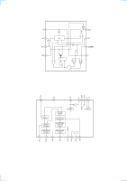
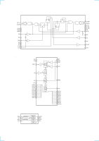
Pin No. Pin Name I/O 51 MD 2 I 52 HW STANDBY I 53 RDS CLOCK I 54 RDS DATA I 55 VOL UP O 56 VOL DOWN O 57 - - 58 U-RESET O 59 U-SREQ I 60 U-MREQ O 61 U-DATA O 62 U-CLOCK O 63 AUBUS-IN I 64 SPEAKER I 65 SPEAKER I 66 POW-KEY IN I 67 AUBUS-OUT O 68 VIRSION IN1 I 69 VIRSION IN 2 I 70 VIRSION IN 3 I 71 VIRSION IN 4 I 72 VIRSION IN 5 I 73 VIRSION OUT 1 O 74 VIRSION OUT 2 O 75 JOG-UP I 76 JOG-DOWN I 77 RESET I 78 FUNCTION UP I 79 FUNCTION DOWN I 80 - - 81 VSS - 82 X0 - 83 X1 - 84 VCC - 85 - - 86 - - 87 LED CLK I 88 LED DATA I 89 LED CE I 90 LED CLR I 91 - - 92 - - 93 MBUS-V1 I 94 MBUS-DVD I 95 MBUS-TV I 96 MBUS-STATUS I 97 - - 98 LAT O 99 RESET O 100 - - Description MD 2 Hardware STANDBY input RDS clock input RDS data input Volume up output Volume down output Not used (Connected to Ground) Reset output (Connected to MB90573 RESET) Slave request and data input (Connected to MB90573 SLV DATA/REQ) Master request output (Connected to MB90573 DISPMR) Master data output (Connected to MB90573 DISP DATA) Master clock output (Connected to MB90573 DISPCLK) Audio bus input Speaker A signal input. Speaker B signal input. POWER-KEY input. Audio bus output Virsion input. Virsion input. Virsion input. Virsion input. Virsion input. Virsion output. Virsion output. Function encoder up input. Function encoder down input. Reset (Display MCU) Rotary encoder input. Rotary encoder input. Not used (Connected to Ground) Ground (Connected to Ground) External ceramic filter 4 MHz is connected to this terminal External ceramic filter 4 MHz is connected to this terminal Power supply +5 V Not used. (Connected to Ground) Not used. (Connected to Ground) LED clock input. LED data input. LED chip eneble input. LED clear input. Not used. (Connected to Ground) Not used. (Connected to Ground) V1 input from MBUS. DVD input from MBUS. TV input from MBUS. STATUS input from MBUS. Not used. (Connected to Ground) Learning microprocessor latch output. Reset. Not used. (Connected to Ground) - 57 -
-
 1
1 -
2
-
3
-
4
-
5
-
6
-
7
-
8
-
9
-
10
-
11
-
12
-
13
-
14
-
15
-
16
-
17
-
18
-
19
-
20
-
21
-
22
-
23
-
24
-
25
-
26
-
27
-
28
-
29
-
 30
30 -
 31
31 -
 32
32 -
 33
33 -
 34
34 -
 35
35 -
 36
36 -
 37
37 -
 38
38 -
 39
39 -
 40
40 -
41
-
42
-
43
-
44
-
45
-
46
-
47
-
48
-
49
-
50
-
51
-
52
-
53
-
54
-
55
-
56
-
57
-
58
-
59
-
60
-
61
-
62
-
63
-
64
 |
 |