Sony VGC-RA839G Quick Start Guide - Page 57
To connect the telephone and modem
 |
View all Sony VGC-RA839G manuals
Add to My Manuals
Save this manual to your list of manuals |
Page 57 highlights
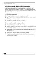
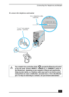
Connecting the Telephone and Modem To connect the telephone and modem RJ-11 telephone cable (optional) "1-to-2" jack adapter (splitter - optional) Your computer has a protective sticker covering the Ethernet port located on the rear panel. Connect 10BASE-T, 100BASE-TX, or 1000BASE-T cables to the Ethernet port, depending on your computer's Ethernet port specification. Using incorrect cables or a telephone cable may result in an electric current overload that can cause a malfunction, excessive heat, or fire in the Ethernet port. For help on connecting to a network, see your network administrator. 57
-
 1
1 -
2
-
3
-
4
-
5
-
6
-
7
-
8
-
9
-
10
-
11
-
12
-
13
-
14
-
15
-
16
-
17
-
18
-
19
-
20
-
21
-
22
-
23
-
24
-
25
-
26
-
27
-
28
-
29
-
30
-
31
-
32
-
33
-
34
-
35
-
36
-
37
-
38
-
39
-
40
-
41
-
42
-
43
-
44
-
45
-
46
-
47
-
48
-
49
-
50
-
51
-
 52
52 -
 53
53 -
 54
54 -
 55
55 -
 56
56 -
 57
57 -
 58
58 -
 59
59 -
 60
60 -
 61
61 -
 62
62 -
63
-
64
-
65
-
66
-
67
-
68
-
69
-
70
-
71
-
72
-
73
-
74
-
75
-
76
-
77
-
78
-
79
-
80
-
81
-
82
-
83
-
84
 |
 |
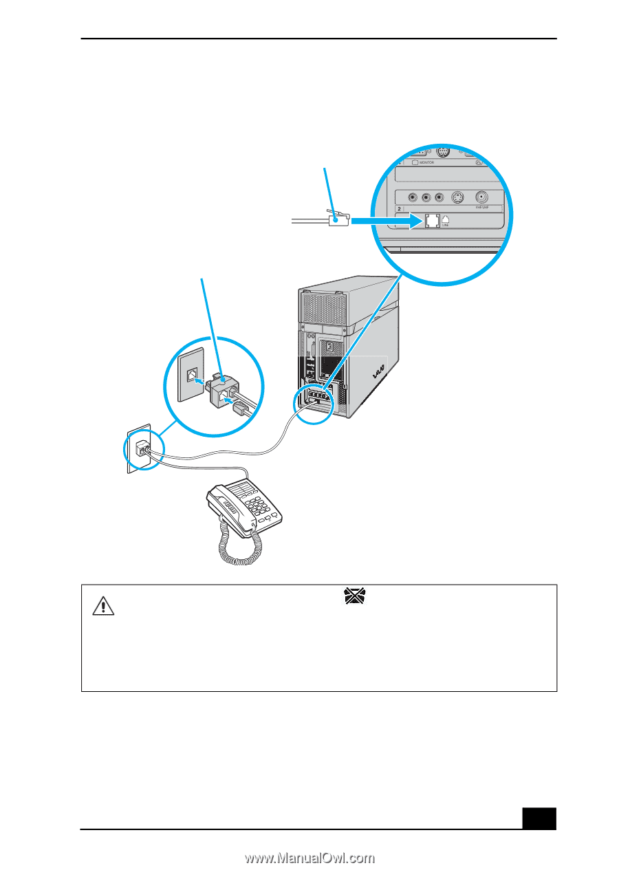
Connecting the Telephone and Modem
57
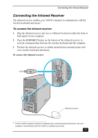
To connect the telephone and modem
Your computer has a protective sticker
covering the Ethernet port located
on the rear panel. Connect 10BASE-T, 100BASE-TX, or 1000BASE-T cables to
the Ethernet port, depending on your computer’s Ethernet port specification.
Using incorrect cables or a telephone cable may result in an electric current
overload that can cause a malfunction, excessive heat, or fire in the Ethernet
port. For help on connecting to a network, see your network administrator.
“1-to-2” jack adapter
(splitter - optional)
RJ-11 telephone cable
(optional)