Toshiba Satellite L755 User Manual - Page 38
Front with the display open, Battery release latch, Memory module slot - lcd
 |
View all Toshiba Satellite L755 manuals
Add to My Manuals
Save this manual to your list of manuals |
Page 38 highlights
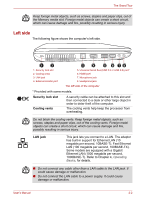
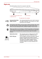
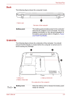
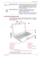
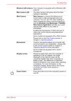
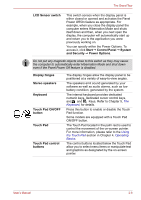
The Grand Tour Battery release latch Memory module slot Slide and hold this latch into its "Unlock" position in order to release the battery pack for removal. For more detailed information on removing the battery pack please refer to Chapter 6, Power and Power-Up Modes. The memory module slot allows for the installation, replacement and removal of additional memory module. Refer to the Additional memory module section in Chapter 3, Hardware, Utilities and Options. Front with the display open This section shows the computer with the display panel open. In order to open the display, lift the display panel up and position it at a comfortable viewing angle for you. 3 2 4 1 5 8 9 6 7 8 9 11 10 12 13 1. Wireless LAN antenna (not shown) 2. Web Camera* 3. Web Camera LED* 4. Microphone* 5. Display screen 6. Power button 7. LCD Sensor switch (not shown) 8. Display hinges 9. Stereo speakers 10. Keyboard 11. Touch Pad ON/OFF button* 12. Touch Pad 13. Touch Pad control buttons The front of the computer with the display panel open * Provided with some models. Product appearance depends on the model you purchased. User's Manual 2-6
-
 1
1 -
2
-
3
-
4
-
5
-
6
-
7
-
8
-
9
-
10
-
11
-
12
-
13
-
14
-
15
-
16
-
17
-
18
-
19
-
20
-
21
-
22
-
23
-
24
-
25
-
26
-
27
-
28
-
29
-
30
-
31
-
32
-
 33
33 -
 34
34 -
 35
35 -
 36
36 -
 37
37 -
 38
38 -
 39
39 -
 40
40 -
 41
41 -
 42
42 -
 43
43 -
44
-
45
-
46
-
47
-
48
-
49
-
50
-
51
-
52
-
53
-
54
-
55
-
56
-
57
-
58
-
59
-
60
-
61
-
62
-
63
-
64
-
65
-
66
-
67
-
68
-
69
-
70
-
71
-
72
-
73
-
74
-
75
-
76
-
77
-
78
-
79
-
80
-
81
-
82
-
83
-
84
-
85
-
86
-
87
-
88
-
89
-
90
-
91
-
92
-
93
-
94
-
95
-
96
-
97
-
98
-
99
-
100
-
101
-
102
-
103
-
104
-
105
-
106
-
107
-
108
-
109
-
110
-
111
-
112
-
113
-
114
-
115
-
116
-
117
-
118
-
119
-
120
-
121
-
122
-
123
-
124
-
125
-
126
-
127
-
128
-
129
-
130
-
131
-
132
-
133
-
134
-
135
-
136
-
137
-
138
-
139
-
140
-
141
-
142
-
143
-
144
-
145
-
146
-
147
-
148
-
149
-
150
-
151
-
152
-
153
-
154
-
155
-
156
-
157
-
158
-
159
-
160
-
161
-
162
-
163
-
164
-
165
-
166
-
167
-
168
-
169
-
170
-
171
-
172
-
173
-
174
-
175
-
176
-
177
-
178
-
179
 |
 |